

IBM PS/2 Model 50: Difference between revisions
Rebuilt against IBM's Model 50 Technical Reference and Hardware Maintenance Reference (both hosted here) plus ardent-tool. Corrections: the RTC is a Motorola MC146818A soldered at ZM47 with a SEPARATE 6 V lithium battery (72X8498) in the battery/speaker assembly (FRU 33F5950), not a Dallas DS1287/DS12887 module; there is NO -5 V rail (IBM lists only +5, +12 and -12); the BIOS is four 27256s at ZM13-ZM16, not two 64 KB devices; the four channel connectors are described as IBM describes them (o... |
P4 verification: remove the now-duplicated manual link bullet (superseded by the fuller documentation line) |
||
| (One intermediate revision by the same user not shown) | |||
| Line 207: | Line 207: | ||
* [[IBM PS/2 Model 60]] — the tower sibling | * [[IBM PS/2 Model 60]] — the tower sibling | ||
* [[IBM PS/2 Model 30]] · [[IBM PS/2 Model 70]] · [[IBM PS/2 Model 80]] | * [[IBM PS/2 Model 30]] · [[IBM PS/2 Model 70]] · [[IBM PS/2 Model 80]] | ||
* [[IBM PS2 Model 50 Technical Reference (May 1988)]] · [[IBM PS2 Model 50 Hardware Maintenance Reference]] & | * '''IBM documentation hosted here:''' [[IBM PS2 Model 50 Technical Reference (May 1988)]] · [[IBM PS2 Model 50 Technical Reference (October 1990)]] · [[IBM PS2 Model 50 Hardware Maintenance Reference]] · [[IBM PS2 Model 50 Schematics]] | ||
{{Navbox-IBMComputers|state=collapsed}} | {{Navbox-IBMComputers|state=collapsed}} | ||
[[Category:IBM]] | [[Category:IBM]] | ||
Latest revision as of 00:20, 25 September 2026
 | |
 | |
| IBM PS/2 Model 50 (8550) | |
| Specifications | |
|---|---|
| Developer | IBM Entry Systems Division, Boca Raton |
| Manufacturer | IBM |
| Type | Mid-range desktop personal computer |
| Released | 2 April 1987 (Model 50); June 1988 (Model 50 Z) |
| CPU | Intel 80286 @ 10 MHz, 1 wait state (Model 50); 0 wait states (Model 50 Z) |
| Memory | 1 MB on the system board; 7 MB system maximum via channel memory |
| Storage | 1.44 MB 3.5" diskette; 20 MB or 30 MB fixed disk on an ST-506 adapter, or 60 MB DBA drive on a riser |
| Display | VGA integrated on the system board, 256 KB video memory |
| Sound | PC speaker |
| Dimensions | 360 mm W × 420 mm D × 140 mm H |
| Weight | 9.55 kg (21 lb) |
| OS / Firmware | IBM PC DOS 3.3 and later; IBM OS/2 1.x; IBM AIX PS/2 |
| Predecessor | IBM PC AT (5170) |
| Successor | IBM PS/2 Model 70 |
| Model no. | 8550 |
The IBM Personal System/2 Model 50 (machine type 8550) is the entry-level Micro Channel PS/2: the cheapest of the original four models to get both MCA and VGA. It was announced on 2 April 1987 at a purchase price of US$3,595 alongside the IBM PS/2 Model 30, IBM PS/2 Model 60 and IBM PS/2 Model 80.[1]
A revised Model 50 Z (8550-031 and -061) followed in June 1988 with faster memory and zero-wait-state operation.[2]
Submodels
[edit | edit source]| Submodel | Wait states | Memory | Fixed disk | Released |
|---|---|---|---|---|
| 8550-021 | 1 | 1 MB, two 512 KB modules at about 150 ns | 20 MB, 80 ms average access | April 1987 |
| 8550-031 | 0 | 72-pin 85 ns (or 120 ns) parity module | 30 MB, 39 ms | June 1988 |
| 8550-061 | 0 | 72-pin 85 ns (or 120 ns) parity module | 60 MB, 27 ms | June 1988 |
Memory and drive figures above are IBM's own.[3][2]
Architecture
[edit | edit source]The Model 50 planar exists as P/N 90X9161 and P/N 15F6969; the Model 50 Z planar is FRU 90X9533.[4][5]
| Designator | Device |
|---|---|
| ZM36 | Intel 80286, 10 MHz |
| ZM55 | 80287 math coprocessor socket |
| ZM47 | Motorola MC146818A real-time clock |
| Y3 | 32.768 kHz crystal (real-time clock) |
| ZM13–ZM16 | ROM BIOS, four 27256 devices (32 KB each, 128 KB total) |
| ZM12 | 72X7377 DMA controller |
| ZM71 | 72X7385 bus controller |
| ZM74 | 72X8299 I/O controller |
| ZM75 | Intel 8272A diskette controller |
| ZM82 | Intel P8042AH keyboard controller |
| ZM84 | NS16550 UART |
| ZM96, ZM104 | 8259A interrupt controllers |
| ZM109 | 72X8287 VGA controller |
| ZM127 | Inmos IMSG171P-35 colour look-up table |
| ZM102–ZM117 (eight devices) | 4464 DRAM — 256 KB of video memory |
| ZM21, ZM22 | 30-pin SIMM sockets |
| J1 | Battery / speaker connector |
| J5 | Diskette riser slot |
| J9 | Fan connector |
| J10 | 16-bit channel connector, dedicated to the fixed-disk adapter |
| J11 | 16-bit channel connector with the auxiliary video extension |
| J12, J13 | 16-bit channel connectors |
| F1 | 250 V / 3 A keyboard and mouse fuse |
The system board carries 128 KB of ROM, a 64-byte CMOS RAM with the real-time clock, 256 KB of video memory, eight DMA channels, 16 levels of level-sensitive interrupts, the keyboard and auxiliary-device connectors with password security, the diskette controller (720 KB and 1.44 MB), an RS-232C serial controller and a bidirectional parallel controller.[6]
Real-time clock and battery
[edit | edit source]The Model 50's clock is not a Dallas module. It is a Motorola MC146818A soldered to the planar at ZM47, timed by the 32.768 kHz crystal at Y3, and backed by a separate 6 V lithium battery that lives in the battery and speaker assembly and plugs into J1.[4][6] IBM's maintenance reference states that a 6 Vdc lithium battery maintains voltage to the real-time clock and CMOS RAM when the supply is off, and that the cover can be locked to prevent battery removal and the loss of the power-on password and configuration.[6][7]
The assembly is FRU 33F5950 and the battery itself is IBM part 72X8498 — a 6 V two-cell lithium pack equivalent to a CR-P2 / DL223A camera battery. IBM's own caution is to use only that part, and IBM retain tip H024809 says to replace the battery when it measures below 5.5 Vdc out of the assembly.[8][9][7]
The same assembly is how a forgotten power-on password is cleared: with the machine off, short pins 2 and 3 together if the assembly has pins, or insert a meter lead into connector 1 and short the other end to frame ground if it does not; power on, let POST finish, then remove the short.[7]
Micro Channel
[edit | edit source]Four channel connectors, all 16-bit. One carries the auxiliary video extension, and one is occupied by the fixed-disk adapter, which is why IBM's own announcement and hardware maintenance reference both describe the machine as having three expansion slots.[6][7][1] There are no 32-bit slots and no ISA compatibility.
Storage
[edit | edit source]Diskette
[edit | edit source]A 1.44 MB 3.5-inch drive on a bus adapter at the diskette riser slot. IBM specifies the drive at 300 rpm ±1.5 %, 500 kbps and 80 tracks.[1]
These drives are direct drive — the Mitsubishi MF355C specification gives a DC brushless motor coupled straight to the spindle at 300 rpm, with no belt.[10] Their real failure mode is the surface-mount electrolytics on the logic board going open-circuit or high-ESR, and the corrosion left behind.[11][12]
Fixed disk
[edit | edit source]The drive plugs directly into its adapter in slot J10; there is no ribbon back to the planar. Three adapters were used:[13]
- ST-506 adapters FRU 90X8070 and 90X8642 — the 20 MB (-021) and 30 MB (-031) drives.
- DBA-ESDI riser FRU 90X9441 (bare) and 90X9571 (with BIOS) — the 60 MB drive on the -061.
The desktop "ESDI" drives are not true ESDI. They are Direct Bus Attachment units with the controller integrated into the drive, which is why swapping a bare riser for one with BIOS, or fitting a larger drive from a different family, does not simply work.[13][14]
A drive that spins but is not seen, particularly after long storage, may be suffering stiction rather than an electronic fault.[15]
Power Supply
[edit | edit source]94 W, universal and automatic voltage-sensing — there is no voltage selector switch to set wrongly.[1][7] The unit is an ASTEC AA13621, IBM P/N 90X9527, FRU P/N 90X9366.[16] On the Model 50 the fan is a separate assembly plugged into the planar at J9, not built into the supply.[16]
The Model 50 has no −5 V rail. IBM's hardware maintenance reference lists only three outputs:[7]
| Output | Minimum under-voltage sense level |
|---|---|
| +5.0 Vdc | +4.5 Vdc |
| +12.0 Vdc | +10.8 Vdc |
| −12.0 Vdc | −10.2 Vdc |
The service limits IBM gives for measuring a running machine are wider:[17]
| Rail | Minimum | Maximum |
|---|---|---|
| +5 Vdc | +3.7 V | +6.2 V |
| +12 Vdc | +9.0 V | +15.0 V |
| −12 Vdc | −9.0 V | −15.0 V |
Power off for ten seconds or more before switching back on. The supply generates its 'power good' signal on that basis, and that signal lights the green power-good lamp on the front of the machine. If the green light is not on, the supply is not working properly.[7]
Other IBM figures worth having on the bench: heat output 494 BTU/hr (144.8 W); input 90–137 Vac or 180–265 Vac at 50–60 Hz ±3 Hz, drawing at most 2.7 A on the low range or 1.4 A on the high range; and a maximum allowable 275 mA on the keyboard port and 300 mA on the auxiliary device port.[6][7] Those last two are the numbers to check against when a keyboard or mouse blows the planar fuse.
Chassis
[edit | edit source]A low-profile desktop, 360 mm wide, 420 mm deep and 140 mm high, weighing 9.55 kg.[6] Drives and cards are held by IBM's plastic captive push-pin fittings rather than screws; the machine ships with a snap tool, IBM part 72X8547, stowed inside the system unit in front of the battery.[7] Use it, or a plastic spudger — not a screwdriver. The pins are brittle with age.
The drive-structure removal tool and the planar centring pin are covered in the common-devices procedure for this chassis.[18]
BIOS and Reference Diskette
[edit | edit source]No built-in SETUP. Everything is configured from the model-specific Reference Diskette, which also reads each fitted adapter's ADF (adapter description file) and runs Auto Configuration, and carries Advanced Diagnostics under Ctrl-A. The Model 50 and Model 60 share Reference Diskette v1.08.[19]
If a card's ADF is not on the working Reference Diskette, Auto Configuration cannot complete and POST reports a card-ID mismatch. Copy the ADF from the option diskette onto the working copy first.
Certain adapters — 3270 Connection, Token-Ring and PC Network — have installation restrictions and a configuration backup/restore caution on this chassis.[15]
General Maintenance
[edit | edit source]Opening the machine, the snap tool, card and drive handling, battery replacement and rail checks are in IBM PS/2 Model 50 Maintenance Guide.
Troubleshooting
[edit | edit source]Beep codes, the numeric POST code list, the 161/162/163 clock and battery cluster, card-ID mismatches and dead-system isolation are in IBM PS/2 Model 50 Troubleshooting Guide.
Capacitor Replacement
[edit | edit source]The planar decoupling (surface-mount tantalum and ceramic, not aluminium electrolytic), the 94 W supply and the drive logic boards are in IBM PS/2 Model 50 Capacitor Replacement Guide.
Gallery
[edit | edit source]-
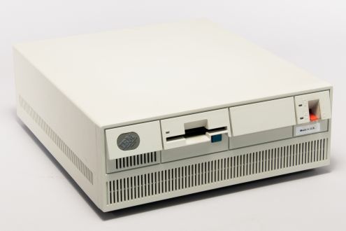 IBM PS/2 Model 50 (8550-021)
 -
 IBM PS/2 Model 50 Z
 -
 Model 50 Z internals
 -
 Model 50 front badge
 -
 Model 50 Z front badge


References
[edit | edit source]- ↑ 1.0 1.1 1.2 1.3 IBM Announcement Letter 187-049, "IBM Personal System/2 Model 50", 2 April 1987, reproduced at ardent-tool.com. Source for the 94-watt automatic voltage-sensing power supply, the four 16-bit I/O slots with one occupied by the disk controller, the 1 MB planar memory expandable to 7 MB, the battery-backed clock and the IBM specification of the 1.44 MB diskette drive (300 rpm ±1.5 %, 500 kbps, 80 tracks).
- ↑ 2.0 2.1 IBM product information document GJAN-43VMLQ, "IBM PS/2 (Model 50 Z) — Technical specifications", mirrored at ardent-tool.com. Source for the June 1988 announcement, zero-wait-state operation, the 72-pin 85 ns (or 120 ns) parity memory module, and the 30 MB (39 ms) and 60 MB (27 ms) drives.
- ↑ IBM product information document GJAN-43VM6G, "IBM PS/2 (Model 50) — Technical specifications", mirrored at ardent-tool.com. Source for the one-wait-state 10 MHz operation, the two 30-pin 512 KB parity DRAM modules at approximately 150 ns, the three 3.5-inch half-height drive bays and the 80 ms access time of the 20 MB drive.
- ↑ 4.0 4.1 8550 Planar, Ardent Tool of Capitalism. Component-designator map for the Model 50 planar (P/N 90X9161 and 15F6969), including F1, the battery/speaker connector, the MC146818A RTC at ZM47 and the slot layout.
- ↑ 8550 Z Planar, Ardent Tool of Capitalism. Component-designator map for the Model 50 Z planar (FRU 90X9533), including F1, the battery/speaker header, the MC146818A RTC at ZM8, the single 72-pin SIMM socket and the 85 ns zero-wait-state memory.
- ↑ 6.0 6.1 6.2 6.3 6.4 6.5 IBM, IBM Personal System/2 Model 50 Technical Reference, May 1988 — hosted on this wiki as File:IBM PS2 Model 50 Technical Reference May88.pdf. Figure 1-2 "System Board Devices and Features", Figure 1-7 "Physical Specifications" and Section 3 "Real-Time Clock/CMOS RAM".
- ↑ 7.0 7.1 7.2 7.3 7.4 7.5 7.6 7.7 7.8 IBM, IBM PS/2 Model 50 Hardware Maintenance Reference, part number 64F3989, form number S64F-3989-00, March 1990 — hosted on this wiki as File:IBM PS2 Model 50 HMR.pdf. Sections 1.2.2 "CMOS RAM", 1.2.7 "Diskette-Drive Controller", 1.2.8 "Keyboard Connector and Pointing-Device Connector", 3.1 "Power Supply" and 3.2 "Power-On Self-Test".
- ↑ Battery/Speaker Assembly, Ardent Tool of Capitalism. Covers Models 50, 50 Z, 60, 65 SX, 70 and 80. Source for FRU numbers 33F5950 and 72X8498, the connector pinouts, the power-on password override and IBM retain tip H024809 (replace the battery below 5.5 V DC, measured out of the assembly).
- ↑ PS/2 Batteries, Ardent Tool of Capitalism, based on content by Bob Eager and Peter H. Wendt. Cross-reference of PS/2 models to battery types: the Model 70 and the Model 80 both take FRU 72X8498, a 6 V two-cell lithium pack equivalent to a CR-P2 / DL223A / EL223AP / K223LA / PC223 camera battery.
- ↑ Mitsubishi Electric, 3.5 inch Flexible Disk Drive Standard Specifications, MF355C, document UGD-0527A, February 1987. File:Mitsubishi MF355C 3.5 inch Diskette Drive Specifications (UGD-0527A, Feb 1987).pdf. Section 3 states that the disk rotation mechanism uses a DC brushless direct-drive motor to rotate the spindle directly at 300 rpm; the drive has no belt.
- ↑ 8580 Diskette Drives, Ardent Tool of Capitalism, content by Fred Spencer and Al Savage. Source for the PS/2 diskette-drive part numbers (P/N 90X6766, FRU 72X8523 card-edge; FRU 64F0162 pin-interface), for Al Savage's teardown of a Mitsubishi MF355W-99M3 identifying five failed surface-mount electrolytics — two 22 µF/16 V, one 1 µF/50 V and two 0.22 µF/50 V — for the diskette-controller dirt problem under the power-supply fan, and for Peter Wendt's list of mechanical causes of a 162 at POST.
- ↑ PS/2 Surface Mount Capacitors, ibmfiles.com. Community teardown source; documents surface-mount electrolytic failure and pad corrosion on PS/2 Mitsubishi diskette drives and on the DBA hard-drive logic boards, and the technique of fitting through-hole parts to the surface-mount pads.
- ↑ 13.0 13.1 8550 HDD Adapters, Ardent Tool of Capitalism. Source for the three Model 50 drive adapters (the ST-506 adapters FRU 90X8070 and 90X8642, the bare DBA-ESDI riser FRU 90X9441 and the DBA-ESDI riser with BIOS FRU 90X9571), for the drive FRU numbers and for Peter Wendt's explanation that the desktop "ESDI" drives are integrated drive-plus-controller units rather than true ESDI.
- ↑ IBM DBA-ESDI Hard Drives, Ardent Tool of Capitalism. Source for the list of systems using Direct Bus Attachment (the Model 70 by drive-riser connector), the 2 × 36-pin edge-connector pinout transcribed from the Model 70 technical reference, and the component map of the WD387 60 MB drive logic board.
- ↑ 15.0 15.1 Known Problems — Experience, RETAIN Tips, ECAs, Ardent Tool of Capitalism. Source for Peter Wendt's account of hard-disk stiction and the recovery options, and for IBM retain tip H005662, the adapter installation restrictions and configuration backup/restore caution for the 3270 Connection, Token-Ring and PC Network adapters in the 8550, 8555, 8560, 8565, 8570, 8580 and 9585.
- ↑ 16.0 16.1 8550 / 8570 / 756x — Power Supply, Ardent Tool of Capitalism (Louis Ohland / Tomáš Slavotínek). Secondary source; it reproduces IBM's own power-supply connector pinout, test-voltage table and FRU data for the 8550. Source for the 50-pin edge-connector pinout, the ASTEC AA13621 identification, the 94 W rating, the security-Torx case fixings, the two internal fuses and the external fan part numbers.
- ↑ IBM, IBM Personal System/2 Hardware Maintenance Manual, S52G-9971-02, October 1994 — hosted on this wiki as File:IBM PS2 HMM S52G-9971 Oct 1994.pdf. Sections "Power Supply Voltage Check", "System-Unit Power Supplies", "Numeric Error Codes" and the Model 50 / Model 60, 65, 80 parts catalogues.
- ↑ 8550 and 8570 — Common Devices, Ardent Tool of Capitalism. Source for the cover removal and locked-case procedures and for the planar removal sequence, including the drive-structure removal tool stowed under the battery/speaker assembly and the planar centring pin.
- ↑ 8560 Planar, Ardent Tool of Capitalism. Component-designator map for the Model 60 planar (FRU 72X8538), including F1 (5MF 3 A / 250 V), J3 power connector, J14 battery/speaker connector, the MC146818A RTC at ZM6, the µPD446C-15L 2 KB NVRAM at ZM5, the four 30-pin SIMM sockets and the eight Micro Channel slots.
Related Pages
[edit | edit source]- IBM PS/2 Model 50 Maintenance Guide · IBM PS/2 Model 50 Troubleshooting Guide · IBM PS/2 Model 50 Capacitor Replacement Guide
- IBM PS/2 Model 60 — the tower sibling
- IBM PS/2 Model 30 · IBM PS/2 Model 70 · IBM PS/2 Model 80
- IBM documentation hosted here: IBM PS2 Model 50 Technical Reference (May 1988) · IBM PS2 Model 50 Technical Reference (October 1990) · IBM PS2 Model 50 Hardware Maintenance Reference · IBM PS2 Model 50 Schematics