

Atari XE Game System
.jpg) | |
| Atari XE Game System | |
| Specifications | |
|---|---|
| Manufacturer | Atari Corporation |
| Type | Home video game console / home computer |
| Released | Late 1987 |
| Discontinued | December 1991 |
| CPU | MOS Technology 6502C @ 1.79 MHz (NTSC) / 1.77 MHz (PAL) |
| Memory | 64 KB RAM (two 64K x 4 DRAMs); operating system ROM with built-in Missile Command |
| Storage | ROM cartridge; SIO peripherals (disk, cassette) with the keyboard attached |
| Display | 40 x 24 text, up to 320 x 192 pixels |
| Sound | POKEY: four audio channels |
| OS / Firmware | Atari XE Operating System; Atari BASIC Rev. C |
| Predecessor | Atari 7800 |
| Model no. | XEGS (board C100417) |
The Atari XE Game System (XEGS) is an Atari 65XE in a console case with a detachable keyboard, released in late 1987 and the last hardware in the Atari 8-bit line. Without the keyboard it behaves as a games console and starts its built-in Missile Command; with the keyboard attached it boots to Atari BASIC exactly like an XE computer.[1]
Atari's field service manual for the XE line carries the XEGS schematic and silkscreen as "XE-System Assembly C100417", and is the source for the hardware detail below.[2]
History
Antic recorded the pitch that produced the machine: Atari executives asked the heads of several major toy store chains which product they would rather sell, "the powerful 65XE home computer for about $80, or a fancy new game system for about $150", and were told to keep the computer.[1]
Atari sold 100,000 XE Game Systems in the United States over the 1987 Christmas season - every unit it manufactured that year.[3] That figure is for the launch season in one market; no verified total-production or lifetime-sales figure for the XEGS could be found, and none is given here. A Flight Simulator II cartridge was included with the keyboard component.[3]
Atari discontinued the XEGS with the rest of the 8-bit line in December 1991.
Hardware
The XEGS is the 65XE design rearranged for a console case. Matthew Ratcliff, writing in Antic in 1988 after opening one, counted a total of only 17 chips on the board.[1]
Memory
There are two RAM chips, not eight: 64K x 4 devices giving the full 64 KB. Atari's schematic for C100417 shows them at U2 and U3 as uPD41464C-12;[2] Ratcliff's machine had Texas Instruments TM54464-12 parts in the same positions.[1] The XL and XE computers use eight 64K x 1 devices instead; the smaller count improves reliability and reduces cost.[1]
Using higher-density ROMs left the updated XE operating system with 8 KB of spare ROM, which Atari filled with Missile Command. The game is bank-switched in and out in the same way Atari BASIC is.[1]
 | Atari's own C100417 schematic sheet duplicates reference designators. U2 appears
on both a 74LS138 and a DRAM, U7 on both ANTIC and the operating-system ROM, and U1 on an LM358, a 4051 and an NE555. U-numbers taken from that sheet cannot be used on their own to identify a device - check the part marking on the chip.[2] |
Custom chips
| Chip | Function |
|---|---|
| ANTIC | Display processor: display-list DMA, playfield modes, scrolling, display list interrupts; also controls bus access and RAM refresh |
| GTIA | Generates colour and luminance from ANTIC's bit stream; player/missile graphics; console key inputs |
| POKEY | Four audio channels, keyboard scanning, SIO serial port, timers and interrupts, paddle inputs |
| PIA (6520) | Controller port I/O and peripheral control lines |
| FREDDIE | Memory controller; also generates the CPU clock |
| MMU | Address decoding and bank selection |
Source: Atari's C100417 schematic.[2]
Ports
- Power input - 7-pin DIN, J7, the same connector and wiring as the XE computers:
pins 1, 4 and 6 are +5 V, pins 3, 5 and 7 ground, pin 2 the shield.[2]
- SIO port - 13-pin, for disk drives, cassette, printers and modems. Pin 10 is ready,
pin 12 unused; there is no supply rail on this connector.[2]
- Composite video and RF outputs with a channel 2/3 switch
- Two 9-pin controller jacks - pin 7 +5 V, pin 8 ground[2]
- Cartridge slot - 30-pin, top-loading
- Enhanced Cartridge Interface - 14-pin edge connector behind the cartridge slot[2]
- Keyboard connector - a standard DB15 female, not a proprietary ribbon socket. Two
brackets at the top of the keyboard case lock under the front of the console.[1]
Inside the detachable keyboard is a small circuit board carrying resistors, capacitors and two CD4051 multiplexers, which decode key presses and send an internal key code back to POKEY in the console; the scanning itself is done by POKEY.[1]
Power
The XEGS takes +5 V DC through the 7-pin DIN socket J7. On the board the rail runs from J7 through the power switch SW1 and the choke L3 to the 1000 uF filter C13.[2]
There is no rectifier and no regulator on the main board. The transformer, bridge rectifier, LM78S05 regulator, 4700 uF reservoir and 100 uF output capacitor are all inside the external brick, which Atari rates at 5 V +/-5%, 1.5 A maximum.[2]
Boot behaviour and self test
- No keyboard attached - the console starts Missile Command automatically.[1]
- Keyboard attached, no cartridge - the console starts Atari BASIC Rev. C. Hold
SELECT at power-on to get Missile Command instead.[1]
- Self test - hold OPTION and press POWER.[4] From a BASIC ready prompt,
 typing BYE also reaches the self test, but BASIC is not switched off when you do, so the
 8 KB under BASIC is not tested and the memory screen shows 40 RAM squares instead of
 48.[1][4]
- From the self test, pressing RESET while holding SELECT goes to Missile
 Command; pressing RESET while holding OPTION from within Missile Command returns to
 the self test; RESET on its own returns to BASIC.[1]
XG-1 light gun
The XG-1 supplied with the deluxe set is a specialised light pen, using the light-pen support built into the Atari 8-bit hardware. Its horizontal position can be read at memory location 564 (LPENH) and its vertical position at 565 (LPENV), with values from 0 to 227.[1]
The readings are not screen coordinates. Pointing at the far left of the display gives about 88; the value rises to 227 at around column 34, then wraps to 0 and rises again to about 30 by column 39. The offset is the delay between a pixel being lit and the sensor reaching POKEY, which latches an internal scan counter. Vertical readings are half the current scan line, varying from about 17 to 115.[1] The gun will not return reliable readings if the display is too dim, which is why light-gun games use unusually bright screens.[1]
Sets
- Basic set - console and a CX40 joystick with a grey base
- Deluxe set - console, detachable keyboard, CX40 joystick and XG-1 light gun
Board
The mainboard is C100417. Atari's schematic for it is figure 2-13 of the XE field service manual and the matching silkscreen is figure 2-14.[2]
Gallery
-
 Atari XE Game System
 -
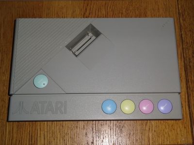 XEGS with the keyboard attached

Related pages
- Atari XE Game System General Maintenance
- Atari XE Game System Troubleshooting Guide
- Atari XE Game System Capacitor Replacement Guide
- Atari 65XE
- Atari 130XE
- Atari 130XE Field Service Manual
References
- ↑ 1.00 1.01 1.02 1.03 1.04 1.05 1.06 1.07 1.08 1.09 1.10 1.11 1.12 1.13 1.14 Matthew Ratcliff, "First Look Inside the XE Game System", Antic Vol. 7 No. 4 (August 1988), reproduced at atarimagazines.com. Source for the DB15 keyboard connector, the two 64K x 4 DRAMs and 17-chip count, the built-in Missile Command bank-switching and the XG-1 light-pen register behaviour.
- ↑ 2.00 2.01 2.02 2.03 2.04 2.05 2.06 2.07 2.08 2.09 2.10 Atari, 130XE Personal Computer Field Service Manual. Section 1 (theory of operation, chip pin assignments, external power supply schematic and rating, connector pinouts), Section 2 (schematics and silkscreens for all seven XE board assemblies), Section 3 (self test and production-test diagnostic error codes). Despite its title it covers the 65XE, the 800XE and the XE Game System as well. Hosted on this wiki: File:Atari 130XE Field Service Manual.pdf.
- ↑ 3.0 3.1 Nat Friedland, "Editorial: Ever-Changing Atari Marketplace", Antic Vol. 7 No. 1 (May 1988), reproduced at atarimagazines.com.
- ↑ 4.0 4.1 Atari Corporation, ATARI XE Game System Owner's Manual. Available at the Internet Archive, item
atari-xegs. Source for the boot behaviour, the self-test procedure and the power-connection description.