

IBM PS/2 Model 80
 | |
 | |
| IBM PS/2 Model 80 (8580) floor-standing tower | |
| Specifications | |
|---|---|
| Developer | IBM Entry Systems Division, Boca Raton |
| Manufacturer | IBM |
| Type | Floor-standing tower personal computer |
| Released | Announced 2 April 1987 (8580-041, -071, -111) |
| CPU | Intel 80386DX at 16 MHz (-041, -071), 20 MHz (-081, -111, -121, -161, -311, -321) or 25 MHz with 64 KB L2 cache (-A16, -A21, -A31); socket for an 80387DX |
| Memory | 1 MB (16 MHz), 2 MB (20 MHz) or 4 MB (25 MHz) as supplied, on two planar memory-expansion connectors taking IBM 80386 memory cards; 4 MB maximum on the 16/20 MHz planars and 8 MB on the 25 MHz planar; 16 MB system maximum using Micro Channel memory adapters |
| Storage | 1.44 MB 3.5-inch diskette drive; fixed disk 44 MB ST-506, 70/115/314 MB ESDI or 80/120/160/320 MB SCSI depending on submodel |
| Display | VGA on the planar, 15-pin D-sub; 640 × 480 graphics, 720 × 400 text, 256 colours or 64 shades of grey |
| Sound | Speaker in the battery/speaker assembly |
| Dimensions | 165 mm wide (318 mm with feet extended) × 483 mm deep × 597 mm high |
| Weight | 23.1 kg (8580-041 and -071); 20.6 kg with one fixed disk (25 MHz models) |
| OS / Firmware | IBM PC DOS 3.30 and later; IBM OS/2 1.x; IBM AIX PS/2; Novell NetWare |
| Model no. | 8580 |
The IBM Personal System/2 Model 80 386 (IBM machine type 8580) is IBM's 80386DX-based floor-standing tower, announced on 2 April 1987 with the rest of the original PS/2 line. It uses the same tower chassis, side cover, drive support structure, power-supply form factor and battery/speaker assembly as the Model 60, with a 32-bit Micro Channel planar in place of the Model 60's 16-bit one.[1][2]
Three quite different planars were sold under the 8580 name across six years, and the 25 MHz machines in particular have little in common with the 1987 original: a Japanese-designed board with an 82385 cache subsystem, SCSI as standard and a different base frame.[3][4][5]
Submodels
| Submodel | Processor | Fixed disk | Micro Channel slots | Announced | US launch price |
|---|---|---|---|---|---|
| 8580-041 | 80386DX-16 | 44 MB ST-506 | 3 × 32-bit, 5 × 16-bit (1 AVE) | 2 April 1987 | $6,995 |
| 8580-071 | 80386DX-16 | 70 MB ESDI | 3 × 32-bit, 5 × 16-bit (1 AVE) | 2 April 1987 | $8,495 |
| 8580-111 | 80386DX-20 | 115 MB ESDI | 3 × 32-bit, 5 × 16-bit (1 AVE) | 2 April 1987 | $10,995 |
| 8580-311 | 80386DX-20 | 314 MB ESDI | 3 × 32-bit, 5 × 16-bit (1 AVE) | — | $13,995 |
| 8580-081 | 80386DX-20 | 80 MB SCSI | 3 × 32-bit, 5 × 16-bit (1 AVE) | — | — |
| 8580-121 | 80386DX-20 | 120 MB SCSI | 3 × 32-bit, 5 × 16-bit (1 AVE) | — | — |
| 8580-161 | 80386DX-20 | 160 MB SCSI | 3 × 32-bit, 5 × 16-bit (1 AVE) | — | — |
| 8580-321 | 80386DX-20 | 320 MB SCSI | 3 × 32-bit, 5 × 16-bit (1 AVE) | — | — |
| 8580-A16 | 80386DX-25, 64 KB cache | 160 MB SCSI | 4 × 32-bit, 4 × 16-bit (2 AVE) | — | — |
| 8580-A21 | 80386DX-25, 64 KB cache | 120 MB SCSI | 4 × 32-bit, 4 × 16-bit (2 AVE) | 20 March 1990 | $10,695 |
| 8580-A31 | 80386DX-25, 64 KB cache | 320 MB SCSI | 4 × 32-bit, 4 × 16-bit (2 AVE) | 20 March 1990 | $13,195 |
Note that the 25 MHz machines are SCSI, not ESDI, and that the entry-level -041 uses an ST-506 drive rather than ESDI. IBM introduced SCSI to the PS/2 line as a standard feature with the -A21 and -A31.[5][3]
Micro Channel Slots
Every 8580 has eight slots, but the split is not what the total suggests and it changes with the planar. There is no 8-bit slot and there are not seven 32-bit slots.
- 16 MHz and 20 MHz planars: three 32-bit slots (J1, J2, J4) and five 16-bit slots (J3, J5, J6, J7, J8), one of which — J6 — carries the auxiliary video extension. IBM's announcement describes it as "eight I/O bus slots with five 16-bit and three 16/32-bit (one 16-bit slot is occupied by the disk controller adapter)".[1][9][10]
- 25 MHz planar: four 32-bit slots with Matched Memory Extension (J10–J13) and four 16-bit slots (J14, J15, and J6 and J7 with the auxiliary video extension), with one 16-bit slot occupied by the SCSI controller. IBM quotes "seven available adapter slots".[4][5]
Because the on-board VGA provides the base video capability there is no base video extension slot on the planar — only the auxiliary video extension slots.[2]
Planar Types
| Type | Speed | Models | FRU | Memory connectors |
|---|---|---|---|---|
| Type 1 | 16 MHz | -041, -071 | 33F8416 (P/N 72X7492) | J15, J16 |
| Type 2 | 20 MHz | -081, -111, -121, -161, -311, -321 | 33F8506 / 92F0756 / 92F0767 (P/N 90X7390) | J15, J16 |
| Type 3 | 25 MHz | -A16, -A21, -A31 | 34F0022 (P/N 33F5571) or 85F0046 (P/N 91F7513) | J8, J9 |
The 25 MHz planar is a Japanese design — it is the board used in the PS/55 Model 5570-Vxx — and it shares its core logic with the 25 MHz Model 70 planar rather than with the earlier 8580 boards.[4]
The two base frame assemblies are not interchangeable. FRU 64F0157 is used on the -041 through -321 and contains a metal back plane required for EMC, which should not be removed. FRU 64F0158 is used on the -A16, -A21 and -A31 and has no back plane, because that planar has components on its solder side.[3]
Planar
- Processor. 80386DX soldered or socketed on the planar — U13 on the Type 1, U131 on the Type 2, U96 on the Type 3 — with a socket for an 80387DX beside it.[9][10][4]
- Cache. None on the 16 and 20 MHz planars. The 25 MHz planar carries an Intel 82385-25 cache controller (U54) and eight Mitsubishi M5M5178P-33 8 K × 8 SRAMs, giving 64 KB of L2.[4][6]
- Memory. Two memory-expansion connectors on the planar — J15 and J16 on the 16/20 MHz boards, J8 and J9 on the 25 MHz board — which take IBM's own 80386 planar memory cards. These are not 72-pin SIMM sockets and PS/2 SIMMs do not fit them. The 16 and 20 MHz planars take 1 MB and 2 MB 80 ns cards to a board maximum of 4 MB; the 25 MHz planar supports 8 MB using 4 MB System Memory Boards. Beyond that, memory goes on Micro Channel adapters, to a system ceiling of 16 MB.[11][9][4][6]
- Real-time clock. A Motorola MC146818A soldered to the planar — U187 on the Type 1, U186 on the Type 2, U132 on the Type 3 — with a 32.768 kHz crystal beside it, plus a separate 2 K × 8 SRAM holding the Micro Channel configuration. There is no Dallas RTC module on this planar and no battery inside the clock chip.[9][10][4]
- Battery. A separate 6 V two-cell lithium pack, FRU 72X8498, in the battery/speaker assembly FRU 33F5950, connected to the planar at J18 (Type 1 and 2) or J19 (Type 3).[12][13]
- Video. VGA on the planar — a 72X8287 or 90X8941 VGA controller, an INMOS IMSG171 RAMDAC and eight 64 K × 4 DRAMs for 256 KB of video memory. 720 × 400 in text mode, 640 × 480 in graphics, 256 colours or 64 shades of grey. Composite video is not supported.[9][10][2]
- Fuses. The 25 MHz planar carries three: F2 at 1 A, F3 at 1.5 A and F4 at 2.0 A, with pads for a fourth.[4]
- Ports. VGA (HD15), serial (DB-25), parallel, auxiliary device and keyboard along the rear edge. The 25 MHz machines' parallel port supports DMA transfers.[9][5]
Warning. Some non-IBM graphics adapters drive the VGA signals rather than receiving them. Fitting two adapters that both drive VGA will damage both.[2]
What Actually Fails
The Model 80 planar does not carry surface-mount aluminium electrolytic capacitors. Photographs of the Type 1 and Type 2 planars show through-hole dipped tantalum beads and surface-mount ceramics for rail decoupling; there are no electrolytic cans on the board to leak. The "PS/2 plague" that damages some PS/2 assemblies is not this board's failure mode.[9][10]
What does fail, in rough order of how often you will meet it:
- Dust on the planar under the power-supply fan. The supply's fan draws household dust directly onto a sensitive area of the board. Conductive dust between IC pins produces lost configuration, a wildly wrong clock and disk read/write errors — faults that look like a dead battery or a dead drive. On a Model 80 board the ICs in that area are the 8042 keyboard controller, the MC146818A, the diskette controller, the NS16550 UART, the RTC crystal and sometimes an 8259A.[2]
- The power switch. Roughly half of failed Model 80 supplies have failed on a broken power switch — the red ones more often than the white. The same switch was used in IBM 327x and 525x terminals and is known for it; it was available as a spare.[14]
- The diskette drive, whose logic board uses surface-mount electrolytics that go open-circuit or high-ESR.[15]
- The battery pack, which is a consumable.[12]
See IBM PS/2 Model 80 Capacitor Replacement Guide.
Power Supply
The tower supplies share one form factor and one planar pinout across the 8560, 8565 and 8580, but not one rating. IBM's own technical reference lists heat outputs for three:[16][14]
| Rating | Identification | Notes |
|---|---|---|
| 225 W | IBM P/N 72X6665, REV A58491, PEC 3978; also seen as FRU 15F6548 | Fitted to the earlier 8580s. 100–125 V at 4.5 A or 200–240 V at 2.5 A input; +5 V at 27.25 A, +12 V at 7 A, −12 V at 0.39 A output. Red switch. Heat output 350 W/hour |
| 242 W | Later 8580s, including the 25 MHz models | Heat output 375 W/hour |
| 250 W | FRU 57F1600 | Heat output 390 W/hour |
The supply provides three DC rails — +5 V, +12 V and −12 V — plus Power Good and a hard-disk LED line. There is no −5 V rail.[16][14]
Rail limits, the connector pinout and the supply's protection behaviour are on the maintenance page. The 225 W unit is the one PS/2 assembly for which a full component-level schematic exists, so the Model 80 is unusually well served for power-supply repair.[17]
Drive Bays
IBM counts five or six storage positions: four 3.5-inch half-height (two of them accessible from the front) plus one 5.25-inch full-height, which can instead be fitted with two 3.5-inch half-height drives using the SCSI Fixed Disk Drive Kit A.[6] The 25 MHz machines support five internal storage devices as standard and six with an option.[5]
The 44 MB, 70 MB, 115 MB and 314 MB drives are 5.25-inch full-height units; the SCSI drives are 3.5-inch half-height. IBM's published power figures are 31–39 W for the 44–115 MB drives, 35–42 W for the 314 MB drive and 13–19 W for a 3.5-inch SCSI drive — worth knowing before loading a tired supply.[6][14]
| Capacity | Interface | Form factor | Average access |
|---|---|---|---|
| 44 MB | ST-506 | 5.25-inch full height | 40 ms |
| 70 MB | ESDI | 5.25-inch full height | 30 ms |
| 115 MB | ESDI | 5.25-inch full height | 28 ms |
| 314 MB | ESDI | 5.25-inch full height | 23 ms |
| 120 MB | SCSI | 3.5-inch half height | 23 ms |
| 320 MB | SCSI | 3.5-inch half height | 12.5 ms |
Reference Diskette
Configuration is held in CMOS and set from a Reference Diskette rather than a BIOS setup screen — Set Configuration and Automatic Configuration, Set Features, the power-on password functions and Advanced Diagnostics (Ctrl-A). The Model 70 and Model 80 share a Reference Diskette image.[3]
The BIOS on the 8570 and 8580 does not support the IBM SCSI-2 Fast/Wide adapter; that card is supported on the 8590, 8595 and 957x machines only.[3]
Physical and Electrical Specifications
| Item | Value |
|---|---|
| Width × depth × height | 165 mm (318 mm with the feet extended) × 483 mm × 597 mm |
| Weight | 23.1 kg (-041 and -071 as announced); 20.6 kg with one fixed disk (25 MHz models) |
| Heat output | 350, 375 or 390 W/hour depending on which supply is fitted |
| Mains input | 100–125 V or 200–240 V, 50–60 Hz, automatically selected |
| Operating temperature and humidity | 15.6 to 32.2 °C, 8 % to 80 % RH |
| Keyboard port, maximum allowable current | 275 mA |
| Auxiliary device port, maximum allowable current | 300 mA |
| Internal fixed disk drive, maximum current | 1.5 A at +5 V, 2.5 A at +12 V per supply connector |
| 16-bit Micro Channel connector, maximum load | 1.6 A at +5 V, 0.175 A at +12 V, 0.040 A at −12 V |
| 32-bit Micro Channel connector, maximum load | 2.0 A at +5 V, 0.175 A at +12 V, 0.040 A at −12 V |
Common Faults
- Lost configuration, a clock that does not advance, or 161 / 162 / 163 at POST. Check the battery — and then check the planar for dust under the supply fan, which produces the same symptoms.[2][18]
- Machine dead with no fan. Suspect the power switch before the supply electronics.[14]
- 110 parity error, particularly with a bus-master adapter fitted. See the ECA list below; early boards have a documented bus-mastering problem.[3]
- Diskette faults and 6xx errors. Failed surface-mount electrolytics on the drive's logic board, or dirt on the planar's diskette controller.[15]
- 1780 on a -041. IBM's own retain tip says to verify that the fixed disk cables are installed correctly before anything else.[2]
- OS/2 Trap 0002 or NMI errors on a 25 MHz machine with 8 MB on the planar. ECA 051 — see below.[4]
- Linux SCSI failures above 16 MB of RAM. The 8580 restricts DMA to the lower 16 MB; the ibmmca driver needs its unchecked_isa_dma flag set.[3]
Engineering Changes
| ECA | Applies to | Subject |
|---|---|---|
| 008 | -111 below S/N 6019000 and -311 below S/N 6502022, planar FRU 90X7390, with an 80387 fitted | Speaker noise |
| 011 | -111 and -311 with board FRU 33F8415 at EC level a79694 and/or REA 18600149 or lower | 386/387 conflict |
| 031 | Initial planar FRU 90X7390 below EC C00835 | Bus-master adapters; most commonly seen as a 110 parity error |
| 035 | Down-level 8514/A adapters | 8514/A in the 8580 |
| 040 | -311 with a second 314 MB ESDI drive | Drive not coming ready, caused by a fault in the drive logic board |
| 048 | Planars 90X7390 and 33F8415 | Second bus-master ECA, naming specific troublesome adapters |
| 051 | 25 MHz -A16, -A21 and -A31 with 8 MB of planar memory | Intermittent OS/2 Trap 0002 or NMI errors. Physical check: if the modules at U24 and U34, near memory connectors J8 and J9, are marked FCT841, the board qualifies for replacement. Any other marking — F841, 841D, 72F841, 72F841D — is good. Ignore anything printed on the board near the module; read the module itself |
| 069 | Down-level diskette drives on early PS/2 machines including the 8580 | 162 with 601 at POST |
Gallery
-
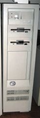 IBM PS/2 Model 80 (8580) floor-standing tower
 -
 Front-bezel "Model 80 386" badge
Related Pages
- IBM PS/2 Model 80 Maintenance Guide
- IBM PS/2 Model 80 Troubleshooting Guide
- IBM PS/2 Model 80 Capacitor Replacement Guide
- IBM PS/2 Model 60 — same tower chassis, 286-class planar
- IBM PS/2 Model 70 — 386-class desktop
- IBM PS/2 Model 50 — 286-class desktop
- Hard Drive Maintenance and Repair
- Floppy Drive Repair
References
- ↑ 1.0 1.1 1.2 1.3 IBM Announcement Letter 187-051, "IBM Personal System/2 Model 80 (8580-041/071)", 2 April 1987, reproduced at ardent-tool.com. Source for the launch prices, the "eight I/O bus slots with five 16-bit and three 16/32-bit (one 16-bit slot is occupied by the disk controller adapter)", the 225-watt universal power supply, and the physical specifications (165.1 × 482.6 × 597.2 mm, 23.1 kg).
- ↑ 2.0 2.1 2.2 2.3 2.4 2.5 2.6 60, 65 SX, and 80 — Common Devices, Ardent Tool of Capitalism. Source for the side-cover and front-bezel removal procedures, the locked-case workaround, IBM retain tip H064300 (1780 on the -041 machines), the dust-under-the-fan cause of lost configuration and disk errors with the list of affected ICs, IBM retain tip H024809 on checking the battery for a minimum of 5.5 V DC, the Mitsubishi/ALPS diskette-drive comparison and "killer caps", Alan Douglas's capacitor-replacement notes, and the on-board VGA capabilities and the multiple-VGA-driver warning.
- ↑ 3.0 3.1 3.2 3.3 3.4 3.5 3.6 3.7 3.8 8580 Common Devices, Ardent Tool of Capitalism. Source for Fred Spencer's submodel table (processor speed, disk interface and capacity, and the 32-bit/16-bit/AVE slot split for every 8580), IBM retain tip H104756 on draining CMOS by grounding the configuration modules, the memory-error codes and memory activation/deactivation behaviour, Peter Wendt's summary of Model 80 ECAs 008, 011, 031, 035, 040, 048, 051 and 069, retain tip H006554 on intermittent 110 parity errors, the 64 MB configuration limit, and retain tip H021673 on the two non-interchangeable base frame assemblies.
- ↑ 4.00 4.01 4.02 4.03 4.04 4.05 4.06 4.07 4.08 4.09 4.10 8580 Type 3 Planar, Ardent Tool of Capitalism. Component-designator map for the 25 MHz planar (FRU 34F0022 / 85F0046): J10–J13 32-bit slots with Matched Memory Extension, J6/J7 16-bit slots with auxiliary video extension, J14/J15 16-bit slots, J8 and J9 memory-expansion connectors, J19 battery/speaker connector, F2/F3/F4 1 A, 1.5 A and 2.0 A fuses, U54 Intel 82385-25 cache controller with eight Mitsubishi M5M5178P-33 8 K × 8 SRAMs, U96 80386DX-25 and U132 MC146818AFN RTC. Also carries the full text of IBM ECA 051.
- ↑ 5.0 5.1 5.2 5.3 5.4 5.5 5.6 IBM Announcement Letter 190-055, "IBM Personal System/2 Model 80 (8580-A21, -A31)", 20 March 1990, reproduced at ardent-tool.com. Source for the -A21 and -A31 announcement date, their 25 MHz 386 with 64 KB cache, SCSI as a standard feature, 4 MB of 80 ns memory, the DMA parallel port, the 242-watt power supply, seven available adapter slots, support for five (optionally six) internal storage devices, and the prices of US$10,695 and US$13,195.
- ↑ 6.0 6.1 6.2 6.3 6.4 6.5 IBM product information document GJAN-43WKBR, "IBM PS/2 (Model 80) — Technical specifications", mirrored at ardent-tool.com. IBM's own summary: announce date 2 April 1987; 16 MHz (041, 071), 20 MHz (1xx), 25 MHz (Axx); 3 32-bit slots on the 0xx/1xx and 4 on the Axx; 1–4 MB on the system board in two sockets, expandable to 16 MB with memory options; cache 0 KB except 64 KB on the Axx; 225 W (242 W on the Axx); drive bays 4 × 3.5-inch half-height plus 1 × 5.25-inch full height; and the interface and access time of every fixed disk offered.
- ↑ IBM Announcement Letter 187-052, "IBM Personal System/2 Model 80 (8580-111)", 2 April 1987, reproduced at ardent-tool.com. Source for the -111's US$10,995 launch price.
- ↑ IBM Announcement Letter 187-150, "IBM Personal System/2 Model 80 (8580-311)", reproduced at ardent-tool.com. Source for the -311's US$13,995 price and the US$6,495 314 MB fixed disk drive feature.
- ↑ 9.0 9.1 9.2 9.3 9.4 9.5 9.6 9.7 8580 Type 1 Planar, Ardent Tool of Capitalism. Component-designator map for the 16 MHz planar (FRU 33F8416): J1/J2/J4 32-bit Micro Channel slots with Matched Memory Extension, J3/J5/J7/J8 16-bit slots, J6 16-bit slot with auxiliary video extension, J15 and J16 memory-expansion connectors, J18 battery/speaker connector, U72 72X8287ESD VGA controller with eight OKI M41464-12 64 K × 4 video DRAMs, U187 Motorola MC146818A RTC and U186 2 K × 8 configuration SRAM.
- ↑ 10.0 10.1 10.2 10.3 10.4 10.5 8580 Type 2 Planar, Ardent Tool of Capitalism. Component-designator map for the 20 MHz planar (FRU 33F8506 / 92F0756 / 92F0767, P/N 90X7390): the same slot arrangement as the Type 1, J15 and J16 memory-expansion connectors, J18 battery/speaker connector, U87 72X8287 VGA with eight TI TMS4464FML-12 video DRAMs, U131 Intel 386DX-20, U186 MC146818A RTC and U146 configuration SRAM. Also links IBM's Model 80 planar schematics.
- ↑ 8580 Planar Memory, Ardent Tool of Capitalism. Catalogue of the IBM planar memory cards used in the 8580's two on-board memory-expansion connectors, with part numbers, DRAM complements and the connector pinout. These cards are specific to the Model 80 and are not 72-pin SIMMs.
- ↑ 12.0 12.1 Battery/Speaker Assembly, Ardent Tool of Capitalism. Source for the assembly FRU 33F5950, the battery FRU 72X8498, both connector pinouts (speaker data, ground, +6 V battery, Clear POP) and the power-on-password clearing procedure for Models 50, 50 Z, 60, 65 SX, 70 and 80.
- ↑ PS/2 Batteries, Ardent Tool of Capitalism, based on content by Bob Eager and Peter H. Wendt. Cross-reference of PS/2 models to battery types: the Model 70 and the Model 80 both take FRU 72X8498, a 6 V two-cell lithium pack equivalent to a CR-P2 / DL223A / EL223AP / K223LA / PC223 camera battery.
- ↑ 14.0 14.1 14.2 14.3 14.4 60, 65 SX, and 80 — Power Supply, Ardent Tool of Capitalism. Secondary source reproducing IBM's 15-pin planar power-connector pinout and service test-voltage table for the 8560/8565/8580, the observed supply variants with their FRU numbers and output ratings, the removal procedure, Peter Wendt's note on the high failure rate of the power switch, and Fred Spencer's fixed-disk power-consumption figures.
- ↑ 15.0 15.1 8580 Diskette Drives, Ardent Tool of Capitalism, content by Fred Spencer and Al Savage. Source for the PS/2 diskette-drive part numbers (P/N 90X6766, FRU 72X8523 card-edge; FRU 64F0162 pin-interface), for Al Savage's teardown of a Mitsubishi MF355W-99M3 identifying five failed surface-mount electrolytics — two 22 µF/16 V, one 1 µF/50 V and two 0.22 µF/50 V — for the diskette-controller dirt problem under the power-supply fan, and for Peter Wendt's list of mechanical causes of a 162 at POST.
- ↑ 16.0 16.1 16.2 IBM, IBM Personal System/2 Model 80 386 Technical Reference, October 1990 — hosted on this wiki as File:IBM PS2 Model 80 Technical Reference Oct90.pdf. Section 1: "Physical Specifications", "Power Supply", "Outputs", "Output Protection", "Voltage Sequencing", "Component Maximum Current" and "Channel Load Current".
- ↑ Eric Schlaepfer ("Tube Time"), IBM PS/2 225 W Power Supply 72X6665 — reverse-engineered schematic, 2024, CC BY-SA 4.0 — hosted on this wiki as File:IBM PS2 225W Power Supply 72X6665 Reverse-Engineered Schematic (Tube Time 2024).pdf. Drawn from a physical 72X6665 / PEC 3978 unit; the only component-level reference published for this supply. IBM did not publish capacitor values for any PS/2 power supply.
- ↑ PS/2 Error Codes and the linked code tables 160–199, 300–999 and 10000–11999, Ardent Tool of Capitalism. Secondary source; the tables reproduce IBM's own symptom-to-FRU lists.