

IBM PCjr: Difference between revisions
Reduce infobox badge size from 250px to 150px |
P4 verification: remove the now-duplicated manual link bullet (superseded by the fuller documentation line) |
||
| (2 intermediate revisions by the same user not shown) | |||
| Line 7: | Line 7: | ||
| manufacturer = IBM | | manufacturer = IBM | ||
| type = Home / consumer personal computer | | type = Home / consumer personal computer | ||
| release date = March | | release date = March 1984 (announced 1 November 1983) | ||
| discontinued = March | | discontinued = March 1985 | ||
| cpu = Intel 8088 @ 4.77 MHz | | cpu = Intel 8088 @ 4.77 MHz | ||
| memory = 64 KB on | | memory = 64 KB on the system board (4860-004) or 128 KB (4860-067); expandable by sidecar | ||
| storage = One 5.25" 360 KB half-height | | storage = One 5.25" 360 KB half-height diskette drive (4860-067 only); cassette port; two ROM cartridge slots | ||
| display = Built-in | | display = Built-in colour/graphics subsystem using a Motorola 6845 CRTC and IBM's Video Gate Array; direct-drive RGB, composite video, and RF through the optional TV Connector | ||
| sound = Texas Instruments ''' | | sound = Texas Instruments '''SN76496N''' complex sound generator, plus the PC speaker, selected by an 8255 | ||
| os = IBM PC DOS 2.1; IBM Cassette BASIC in system ROM, with Cartridge BASIC for Advanced BASIC | |||
| predecessor = none — new product line | |||
| os = IBM PC DOS 2.1 | | successor = none — line ended after one year | ||
| predecessor = | |||
| successor = | |||
| model = 4860 | | model = 4860 | ||
}} | }} | ||
The '''IBM PCjr''' (model '''4860''') was IBM's | The '''IBM PCjr''' (model '''4860''') was IBM's attempt at a low-cost home personal computer. It was announced on 1 November 1983, shipped from March 1984, and withdrawn a year later. It is broadly compatible with the [[IBM PC (5150)]] at the BIOS level, but enough is different — no DMA controller, a different memory map, a gate-array video subsystem with extra graphics modes, a sound chip instead of just a speaker, ROM cartridges instead of expansion slots, an infrared keyboard and a sidecar bus instead of the I/O channel — that it is a separate platform in practice. | ||
== Models == | == Models == | ||
<templatestyles src="Template:StyledTable/styles.css" /> | |||
{| class="wikitable styled-table" style="width:70%; text-align:center;" | {| class="wikitable styled-table" style="width:70%; text-align:center;" | ||
|+'''IBM PCjr submodels''' | |+'''IBM PCjr submodels''' | ||
! Submodel !! On-board RAM !! | ! Submodel !! On-board RAM !! Diskette drive !! Modem | ||
|- | |- | ||
| 4860-004 (Entry) || 64 KB || none || none | | 4860-004 (Entry) || 64 KB || none || none | ||
|- | |- | ||
| 4860-067 (Enhanced) || 128 KB || 360 KB 5.25 | | 4860-067 (Enhanced) || 128 KB || 360 KB 5.25-inch || optional internal | ||
|} | |} | ||
== Architecture == | == Architecture == | ||
An '''Intel 8088 at 4.77 MHz''', the same CPU clock as the 5150 and 5160. The machine has '''no DMA controller''', so all I/O including diskette transfer is done by the CPU in tight programmed-I/O loops.<ref name="brutman">Mike Brutman, [https://www.brutman.com/PCjr/pcjr_hardware.html IBM PCjr Hardware]. Long-running community reference for the machine. Source for the split supply description, the short and long Power Board variants rated at 33 W and 45 W, the roughly 400 mA of +5 V left for sidecars on an internally fully configured machine, the behaviour of overloaded sidecar configurations, the existence of power sidecars using the same external transformer, the absence of a DMA controller and its consequences, and the point that the system has no fan of its own while a diskette-equipped machine has a fan on the drive.</ref> | |||
=== Memory === | |||
The system board's 64 KB of RAM is built from '''eight 64K-by-1, 150 ns''' devices — Motorola MCM6665AL15, Texas Instruments TMS4164-15 or equivalent — and has '''no parity'''.<ref name="trjr">IBM, ''IBM PCjr Technical Reference'' — hosted on this wiki as [[:File:IBM PCjr Technical Reference.pdf]] and documented as [[IBM PCjr Technical Reference]]. "System Power Supply" and its Operating Characteristics, Over-Voltage/Over-Current Protection and Connector Specifications subsections for the two-stage 33 W supply, the transformer's short-circuit-protected extra-low ac output and its "Pin 1 - 17 Vac, Pin 2 - GND, Pin 3 - 17 Vac" connector specification, the internal Power Board that converts that ac to three dc levels, the +5 V / +12 V / −6 V rails with their load currents and regulation tolerances, the 1.5 A minimum +5 V load required for −6 V to be present, the input requirements, the power available at the I/O connector on a fully configured machine, and the input and output protection tables including the five-second reset time. "Hardware Differences" for cassette BASIC residing in system ROM and cartridge BASIC providing Advanced BASIC capability in ROM.</ref> It is mapped at the bottom of the 1 MB address space, and the same physical storage is aliased into the next 64 KB of address space. | |||
The | '''The video buffer is system RAM.''' The same memory serves both as the display buffer and as the 8088's main RAM: the processor can reach it at 00000 upwards, or through a 16 KB window starting at B8000, with a page register deciding which physical page a read or write lands on.<ref name="trjr" /> This is the root of the so-called "PCjr cliff" — software written to assume the 5150's fixed video addresses does not necessarily work here. | ||
== | ROM is built from '''32K-by-8 modules''' (Mostek 38000, TMM23256P or equivalent), also without parity, at 250 ns access and 375 ns cycle time.<ref name="trjr" /> The BIOS, diagnostics and cassette BASIC occupy F0000 to FFFFF; two standard application cartridge areas sit at E0000 and E8000, with D8000 reserved for a further cartridge.<ref name="trjr" /> | ||
=== Video === | |||
The colour/graphics subsystem is implemented with '''a Motorola 6845 CRT controller and IBM's Video Gate Array (VGA, LSI5220)''', a CMOS gate array that generates the storage timing (RAS, CAS, WE), the direct-drive and composite-colour outputs and the status signals.<ref name="trjr" /> The gate array also holds a '''16-entry palette''' used in all alphanumeric modes, with any input maskable off for modes that do not support the full 16 colours.<ref name="trjr" /> | |||
That palette and the shared-RAM buffer are what give the PCjr its two well-known extra modes beyond the standard [[IBM Color Graphics Adapter|CGA]] set — 320 × 200 in 16 colours and 640 × 200 in 4 colours. Tandy reused the same arrangement in the Tandy 1000, which is why software calls them "PCjr/Tandy" modes. | |||
The character generator is an MCM68A316E or equivalent, 350 ns static, pin-compatible with 2716 and 2732 EPROMs — which makes a custom font a realistic modification.<ref name="trjr" /> | |||
Outputs are direct-drive RGB, composite video and the connector for the optional IBM PCjr TV Connector; all are right-angle-mounted connectors through the rear panel.<ref name="trjr" /> | |||
== Sound == | === Sound === | ||
A Texas Instruments '''SN76496N''' complex sound generator: three channels of programmable frequency that can be mixed to form chords, plus a noise generator, each of the four independently attenuated. An '''8255''' selects which source reaches the audio output.<ref name="trjr" /> Output is available on the rear audio jack and, through the TV Connector, on the television's speaker. | |||
== Keyboard == | == Keyboard == | ||
The PCjr keyboard is a 62-key | The PCjr keyboard is a '''low-profile, 62-key, detached keyboard with full-travel keys''', laid out as a standard typewriter keyboard with a function key and cursor-control keys added. The key tops are unmarked for their alternate functions; overlays carry the functional descriptions.<ref name="trjr" /> The first production keyboard used flat rubber keys and was widely criticised; IBM replaced it in 1984 with the full-travel version the technical reference describes. | ||
Inside is an '''80C48''' CMOS microcontroller. It normally sits in a standby power-down mode, wakes on a keypress, scans, transmits, and goes back to sleep — which is why the keyboard runs on '''four batteries''' and has no on/off switch.<ref name="trjr" /> It buffers up to 16 scan codes and performs key debounce. | |||
Two behaviours are specific to this keyboard: | |||
The keyboard | * '''Phantom-key detection.''' Unlike every other keyboard in the IBM PC family, the PCjr's detects invalid combinations of three or more simultaneous keys, sends a hex 55 scan code to its own processor, and discards all keys pressed at that moment. BIOS ignores the resulting code.<ref name="trjr" /> Games that expect three-key combinations will not get them. | ||
* '''The keyboard cord changes the electronics.''' Plugging the optional cord into the modular jack '''disconnects the batteries''' and '''disables the infrared transmitter'''; the −CABLE CONNECTED signal disables the infrared receiver in the system unit as well, so other infrared devices in the room stop interfering.<ref name="trjr" /> | |||
Data reaches the system unit the same way over either link: serially encoded words with '''odd parity''', biphase-encoded by the 80C48 with a 440 µs bit cell, over a simplex link.<ref name="trjr" /> Scan codes are compatible with the PC and XT at the BIOS level; every key is typematic and produces a make code and a break code, the break code being the make code plus hex 80.<ref name="trjr" /> | |||
== Cartridge and Sidecar Expansion == | == Cartridge and Sidecar Expansion == | ||
Two '''ROM cartridge slots''' on the front of the system unit map into the reserved cartridge areas at E0000, E8000 and D8000.<ref name="trjr" /> Cartridge BASIC, which supplies the PCjr's Advanced BASIC capability, is one of these — and because it is in ROM it takes no user memory, unlike ''BASICA'' on a 5150.<ref name="trjr" /> | |||
On the right-hand side of the system unit, behind a removable cover, is a proprietary '''sidecar bus'''. Sidecars latch on and extend the machine horizontally, and can be chained. IBM's own sidecars include the Memory Expansion Attachment, the Parallel Printer Attachment, the Power Expansion Attachment, the internal modem and the Cluster Attachment. The sidecar bus is '''not''' the 5150's I/O channel and PC/XT cards do not fit it. | |||
The power budget is the practical limit on sidecars rather than the bus: see below. | |||
== Power == | |||
'''The external brick is a transformer and nothing else.''' IBM describes the supply as a "33 Watt, three voltage-level, two-stage supply": the first stage is a power transformer providing a single, short-circuit-protected, extra-low '''ac''' output, and the second stage is a printed-circuit board '''inside the system unit''' — the Power Board — which converts that ac into the machine's three dc levels.<ref name="trjr" /> IBM's connector specification for the transformer output reads "Pin 1 – 17 Vac, Pin 2 – GND, Pin 3 – 17 Vac".<ref name="trjr" /> | |||
There is therefore '''no rectifier, no regulator and no high-voltage bulk capacitor inside the brick'''. Rectification, regulation and all of the over-current and over-voltage protection are on the Power Board. | |||
{| class="wikitable styled-table" style="width:85%; text-align:center;" | |||
|+'''IBM PCjr — dc outputs (IBM figures)''' | |||
! Rail !! Minimum load !! Maximum load !! Regulation tolerance | |||
|- | |||
| +5 Vdc || 1.5 A || 3.6 A || ±5% | |||
|- | |||
| +12 Vdc || 0.04 A || 1.2 A || ±5% | |||
|- | |||
| −6 Vdc || 0.0 A || 0.025 A || ±16% | |||
|} | |||
'''There must be a minimum 1.5 A load on +5 V for the −6 V rail to be present at all.'''<ref name="trjr" /> A lightly loaded machine that measures no −6 V is behaving normally. | |||
Protection is split between the two stages:<ref name="trjr" /> | |||
{| class="wikitable styled-table" style="width:85%;" | |||
|+'''IBM PCjr — protection''' | |||
! Where !! Type !! Trip | |||
|- | |||
| Transformer input || Non-resettable fuse, plus thermal / over-current || Not user-resettable | |||
|- | |||
| Power Board, +5 V over-voltage || Fuse || 6.3 ± 0.7 Vdc | |||
|- | |||
| Power Board, +12 V over-voltage || Fuse || 14.4 ± 1.4 Vdc | |||
|- | |||
| Power Board, +5 V over-current || Resettable || about 3.9 A | |||
|- | |||
| Power Board, +12 V over-current || Resettable || 2.2 ± 0.9 A | |||
|} | |||
= | The over-current protection resets by '''removing the fault condition for at least five seconds and then re-applying power'''.<ref name="trjr" /> Over-voltage protection is by fuse, so a Power Board that has been through an over-voltage event may need more than the fault cleared. | ||
A fully configured machine — modem, memory expansion and diskette drive fitted, but no sidecars — leaves roughly '''400 mA of +5 V''' for sidecars.<ref name="brutman" /> That is not much, and a heavy sidecar load produces flaky operation rather than a clean failure. IBM's Power Expansion Attachment adds capacity using a second transformer of the same type. | |||
== General Maintenance == | == General Maintenance == | ||
Cleaning, keyboard and infrared care, sidecar handling, diskette drive care and what to check on the Power Board are in [[IBM PCjr Maintenance Guide]]. | |||
== Troubleshooting == | == Troubleshooting == | ||
POST beep codes, the | POST beep codes, the PCjr error code set, keystroke loss during diskette access, sidecar power problems and infrared interference are in [[IBM PCjr Troubleshooting Guide]]. | ||
== Capacitor Replacement == | == Capacitor Replacement == | ||
Tantalum | Tantalum failure on the system board and electrolytic ageing on the Power Board are in [[IBM PCjr Capacitor Replacement Guide]]. | ||
== Gallery == | == Gallery == | ||
<gallery mode="packed" heights="220"> | <gallery mode="packed" heights="220"> | ||
File:IBM PCjr with display.jpg|IBM PCjr with the IBM 4863 display | File:IBM PCjr with display.jpg|IBM PCjr with the IBM 4863 display | ||
File:IBM PCjr keyboard.png|62-key | File:IBM PCjr keyboard.png|The 62-key cordless keyboard | ||
File:IBM PCjr motherboard.jpg|IBM PCjr | File:IBM PCjr motherboard.jpg|IBM PCjr system board | ||
File:IBM PCjr expanded with sidecars.jpg|IBM PCjr with several sidecars attached | File:IBM PCjr expanded with sidecars.jpg|IBM PCjr with several sidecars attached | ||
File:IBM PCjr internal teardown.jpg| | File:IBM PCjr internal teardown.jpg|Inside the system unit; the Power Board is the second stage of the supply | ||
</gallery> | </gallery> | ||
== | == References == | ||
<references /> | |||
== | == Related Pages == | ||
* [ | * [[IBM PCjr Maintenance Guide]] · [[IBM PCjr Troubleshooting Guide]] · [[IBM PCjr Capacitor Replacement Guide]] | ||
* [[IBM PC (5150)]] — the business sibling | |||
* [ | * [[IBM Cassette BASIC]] | ||
* IBM | * '''IBM documentation hosted here:''' [[IBM PCjr Technical Reference]] · [[IBM PCjr BASIC Reference (June 1983)]] | ||
{{Navbox-IBMComputers|state= | {{Navbox-IBMComputers|state=collapsed}} | ||
[[Category:IBM]] | [[Category:IBM]] | ||
Latest revision as of 00:20, 25 September 2026
 | |
 | |
| IBM PCjr (4860) with its companion IBM 4863 display | |
| Specifications | |
|---|---|
| Developer | IBM Entry Systems Division, Boca Raton |
| Manufacturer | IBM |
| Type | Home / consumer personal computer |
| Released | March 1984 (announced 1 November 1983) |
| Discontinued | March 1985 |
| CPU | Intel 8088 @ 4.77 MHz |
| Memory | 64 KB on the system board (4860-004) or 128 KB (4860-067); expandable by sidecar |
| Storage | One 5.25" 360 KB half-height diskette drive (4860-067 only); cassette port; two ROM cartridge slots |
| Display | Built-in colour/graphics subsystem using a Motorola 6845 CRTC and IBM's Video Gate Array; direct-drive RGB, composite video, and RF through the optional TV Connector |
| Sound | Texas Instruments SN76496N complex sound generator, plus the PC speaker, selected by an 8255 |
| OS / Firmware | IBM PC DOS 2.1; IBM Cassette BASIC in system ROM, with Cartridge BASIC for Advanced BASIC |
| Predecessor | none — new product line |
| Successor | none — line ended after one year |
| Model no. | 4860 |
The IBM PCjr (model 4860) was IBM's attempt at a low-cost home personal computer. It was announced on 1 November 1983, shipped from March 1984, and withdrawn a year later. It is broadly compatible with the IBM PC (5150) at the BIOS level, but enough is different — no DMA controller, a different memory map, a gate-array video subsystem with extra graphics modes, a sound chip instead of just a speaker, ROM cartridges instead of expansion slots, an infrared keyboard and a sidecar bus instead of the I/O channel — that it is a separate platform in practice.
Models
[edit | edit source]| Submodel | On-board RAM | Diskette drive | Modem |
|---|---|---|---|
| 4860-004 (Entry) | 64 KB | none | none |
| 4860-067 (Enhanced) | 128 KB | 360 KB 5.25-inch | optional internal |
Architecture
[edit | edit source]An Intel 8088 at 4.77 MHz, the same CPU clock as the 5150 and 5160. The machine has no DMA controller, so all I/O including diskette transfer is done by the CPU in tight programmed-I/O loops.[1]
Memory
[edit | edit source]The system board's 64 KB of RAM is built from eight 64K-by-1, 150 ns devices — Motorola MCM6665AL15, Texas Instruments TMS4164-15 or equivalent — and has no parity.[2] It is mapped at the bottom of the 1 MB address space, and the same physical storage is aliased into the next 64 KB of address space.
The video buffer is system RAM. The same memory serves both as the display buffer and as the 8088's main RAM: the processor can reach it at 00000 upwards, or through a 16 KB window starting at B8000, with a page register deciding which physical page a read or write lands on.[2] This is the root of the so-called "PCjr cliff" — software written to assume the 5150's fixed video addresses does not necessarily work here.
ROM is built from 32K-by-8 modules (Mostek 38000, TMM23256P or equivalent), also without parity, at 250 ns access and 375 ns cycle time.[2] The BIOS, diagnostics and cassette BASIC occupy F0000 to FFFFF; two standard application cartridge areas sit at E0000 and E8000, with D8000 reserved for a further cartridge.[2]
Video
[edit | edit source]The colour/graphics subsystem is implemented with a Motorola 6845 CRT controller and IBM's Video Gate Array (VGA, LSI5220), a CMOS gate array that generates the storage timing (RAS, CAS, WE), the direct-drive and composite-colour outputs and the status signals.[2] The gate array also holds a 16-entry palette used in all alphanumeric modes, with any input maskable off for modes that do not support the full 16 colours.[2]
That palette and the shared-RAM buffer are what give the PCjr its two well-known extra modes beyond the standard CGA set — 320 × 200 in 16 colours and 640 × 200 in 4 colours. Tandy reused the same arrangement in the Tandy 1000, which is why software calls them "PCjr/Tandy" modes.
The character generator is an MCM68A316E or equivalent, 350 ns static, pin-compatible with 2716 and 2732 EPROMs — which makes a custom font a realistic modification.[2]
Outputs are direct-drive RGB, composite video and the connector for the optional IBM PCjr TV Connector; all are right-angle-mounted connectors through the rear panel.[2]
Sound
[edit | edit source]A Texas Instruments SN76496N complex sound generator: three channels of programmable frequency that can be mixed to form chords, plus a noise generator, each of the four independently attenuated. An 8255 selects which source reaches the audio output.[2] Output is available on the rear audio jack and, through the TV Connector, on the television's speaker.
Keyboard
[edit | edit source]The PCjr keyboard is a low-profile, 62-key, detached keyboard with full-travel keys, laid out as a standard typewriter keyboard with a function key and cursor-control keys added. The key tops are unmarked for their alternate functions; overlays carry the functional descriptions.[2] The first production keyboard used flat rubber keys and was widely criticised; IBM replaced it in 1984 with the full-travel version the technical reference describes.
Inside is an 80C48 CMOS microcontroller. It normally sits in a standby power-down mode, wakes on a keypress, scans, transmits, and goes back to sleep — which is why the keyboard runs on four batteries and has no on/off switch.[2] It buffers up to 16 scan codes and performs key debounce.
Two behaviours are specific to this keyboard:
- Phantom-key detection. Unlike every other keyboard in the IBM PC family, the PCjr's detects invalid combinations of three or more simultaneous keys, sends a hex 55 scan code to its own processor, and discards all keys pressed at that moment. BIOS ignores the resulting code.[2] Games that expect three-key combinations will not get them.
- The keyboard cord changes the electronics. Plugging the optional cord into the modular jack disconnects the batteries and disables the infrared transmitter; the −CABLE CONNECTED signal disables the infrared receiver in the system unit as well, so other infrared devices in the room stop interfering.[2]
Data reaches the system unit the same way over either link: serially encoded words with odd parity, biphase-encoded by the 80C48 with a 440 µs bit cell, over a simplex link.[2] Scan codes are compatible with the PC and XT at the BIOS level; every key is typematic and produces a make code and a break code, the break code being the make code plus hex 80.[2]
Cartridge and Sidecar Expansion
[edit | edit source]Two ROM cartridge slots on the front of the system unit map into the reserved cartridge areas at E0000, E8000 and D8000.[2] Cartridge BASIC, which supplies the PCjr's Advanced BASIC capability, is one of these — and because it is in ROM it takes no user memory, unlike BASICA on a 5150.[2]
On the right-hand side of the system unit, behind a removable cover, is a proprietary sidecar bus. Sidecars latch on and extend the machine horizontally, and can be chained. IBM's own sidecars include the Memory Expansion Attachment, the Parallel Printer Attachment, the Power Expansion Attachment, the internal modem and the Cluster Attachment. The sidecar bus is not the 5150's I/O channel and PC/XT cards do not fit it.
The power budget is the practical limit on sidecars rather than the bus: see below.
Power
[edit | edit source]The external brick is a transformer and nothing else. IBM describes the supply as a "33 Watt, three voltage-level, two-stage supply": the first stage is a power transformer providing a single, short-circuit-protected, extra-low ac output, and the second stage is a printed-circuit board inside the system unit — the Power Board — which converts that ac into the machine's three dc levels.[2] IBM's connector specification for the transformer output reads "Pin 1 – 17 Vac, Pin 2 – GND, Pin 3 – 17 Vac".[2]
There is therefore no rectifier, no regulator and no high-voltage bulk capacitor inside the brick. Rectification, regulation and all of the over-current and over-voltage protection are on the Power Board.
| Rail | Minimum load | Maximum load | Regulation tolerance |
|---|---|---|---|
| +5 Vdc | 1.5 A | 3.6 A | ±5% |
| +12 Vdc | 0.04 A | 1.2 A | ±5% |
| −6 Vdc | 0.0 A | 0.025 A | ±16% |
There must be a minimum 1.5 A load on +5 V for the −6 V rail to be present at all.[2] A lightly loaded machine that measures no −6 V is behaving normally.
Protection is split between the two stages:[2]
| Where | Type | Trip |
|---|---|---|
| Transformer input | Non-resettable fuse, plus thermal / over-current | Not user-resettable |
| Power Board, +5 V over-voltage | Fuse | 6.3 ± 0.7 Vdc |
| Power Board, +12 V over-voltage | Fuse | 14.4 ± 1.4 Vdc |
| Power Board, +5 V over-current | Resettable | about 3.9 A |
| Power Board, +12 V over-current | Resettable | 2.2 ± 0.9 A |
The over-current protection resets by removing the fault condition for at least five seconds and then re-applying power.[2] Over-voltage protection is by fuse, so a Power Board that has been through an over-voltage event may need more than the fault cleared.
A fully configured machine — modem, memory expansion and diskette drive fitted, but no sidecars — leaves roughly 400 mA of +5 V for sidecars.[1] That is not much, and a heavy sidecar load produces flaky operation rather than a clean failure. IBM's Power Expansion Attachment adds capacity using a second transformer of the same type.
General Maintenance
[edit | edit source]Cleaning, keyboard and infrared care, sidecar handling, diskette drive care and what to check on the Power Board are in IBM PCjr Maintenance Guide.
Troubleshooting
[edit | edit source]POST beep codes, the PCjr error code set, keystroke loss during diskette access, sidecar power problems and infrared interference are in IBM PCjr Troubleshooting Guide.
Capacitor Replacement
[edit | edit source]Tantalum failure on the system board and electrolytic ageing on the Power Board are in IBM PCjr Capacitor Replacement Guide.
Gallery
[edit | edit source]-
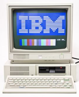 IBM PCjr with the IBM 4863 display
 -
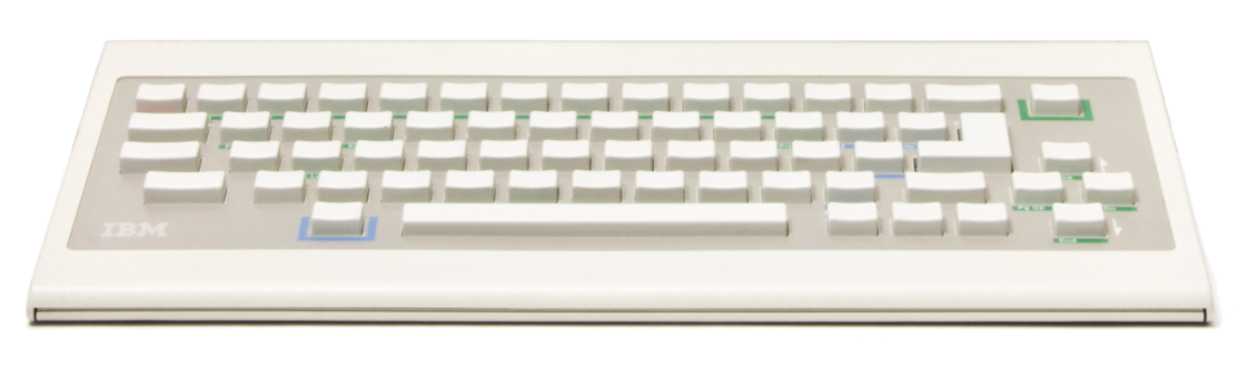 The 62-key cordless keyboard
 -
 IBM PCjr system board
 -
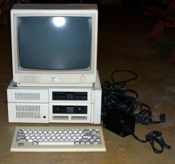 IBM PCjr with several sidecars attached
 -
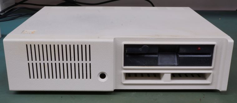 Inside the system unit; the Power Board is the second stage of the supply


References
[edit | edit source]- ↑ 1.0 1.1 Mike Brutman, IBM PCjr Hardware. Long-running community reference for the machine. Source for the split supply description, the short and long Power Board variants rated at 33 W and 45 W, the roughly 400 mA of +5 V left for sidecars on an internally fully configured machine, the behaviour of overloaded sidecar configurations, the existence of power sidecars using the same external transformer, the absence of a DMA controller and its consequences, and the point that the system has no fan of its own while a diskette-equipped machine has a fan on the drive.
- ↑ 2.00 2.01 2.02 2.03 2.04 2.05 2.06 2.07 2.08 2.09 2.10 2.11 2.12 2.13 2.14 2.15 2.16 2.17 2.18 2.19 2.20 2.21 IBM, IBM PCjr Technical Reference — hosted on this wiki as File:IBM PCjr Technical Reference.pdf and documented as IBM PCjr Technical Reference. "System Power Supply" and its Operating Characteristics, Over-Voltage/Over-Current Protection and Connector Specifications subsections for the two-stage 33 W supply, the transformer's short-circuit-protected extra-low ac output and its "Pin 1 - 17 Vac, Pin 2 - GND, Pin 3 - 17 Vac" connector specification, the internal Power Board that converts that ac to three dc levels, the +5 V / +12 V / −6 V rails with their load currents and regulation tolerances, the 1.5 A minimum +5 V load required for −6 V to be present, the input requirements, the power available at the I/O connector on a fully configured machine, and the input and output protection tables including the five-second reset time. "Hardware Differences" for cassette BASIC residing in system ROM and cartridge BASIC providing Advanced BASIC capability in ROM.
Related Pages
[edit | edit source]- IBM PCjr Maintenance Guide · IBM PCjr Troubleshooting Guide · IBM PCjr Capacitor Replacement Guide
- IBM PC (5150) — the business sibling
- IBM Cassette BASIC
- IBM documentation hosted here: IBM PCjr Technical Reference · IBM PCjr BASIC Reference (June 1983)