IBM PC AT Maintenance Guide
The IBM PC AT (5170) is mechanically and electrically more complex than the 5150 or 5160. This guide documents preventive maintenance procedures that apply to all three motherboard revisions of the 5170, together with the points that differ between revisions.
Identifying Your Motherboard
[edit | edit source]Before any maintenance work, identify which motherboard revision you have, because the RAM chip type, the BIOS ROMs, the speed, and the PSU connector pinout differ.
- Type 1 (full-size AT, 13.8" × 12", 6 MHz). 12 MHz crystal Y2, four ROM sockets U17/U27/U37/U47 or two at U27/U47, 41128 stacked DRAM, 2 banks × 256 KB. BIOS 01/10/84.
- Type 2 ("Baby AT", 13.8" × 9.4", 6 MHz). 12 MHz crystal Y2, two ROM sockets U27/U47, 41256 DRAM, 1 bank × 512 KB. BIOS 06/10/85.
- Type 3 (Baby AT, 13.8" × 9.4", 8 MHz). 16 MHz crystal Y2, same RAM as Type 2. BIOS 11/15/85.
If unsure, check the date markings on the BIOS ROM chips and the crystal frequency at Y2. The IBM 5170 service references that ship with the IBM PC AT Troubleshooting Guide include detailed photographs.
Regular Cleaning
[edit | edit source]- Power off and unplug the machine before opening the case.
- Remove the four screws securing the cover, slide the cover forward, and lift off.
- Use a soft brush and low-pressure compressed air to remove dust from the motherboard, expansion cards, drive bays and PSU vents.
- Avoid blowing dust into bearings of the floppy drive, hard drive or PSU fan. Hold the fan blade with a finger if using compressed air.
- Reseat all expansion cards and the keyboard cable.
PSU Voltage Checks
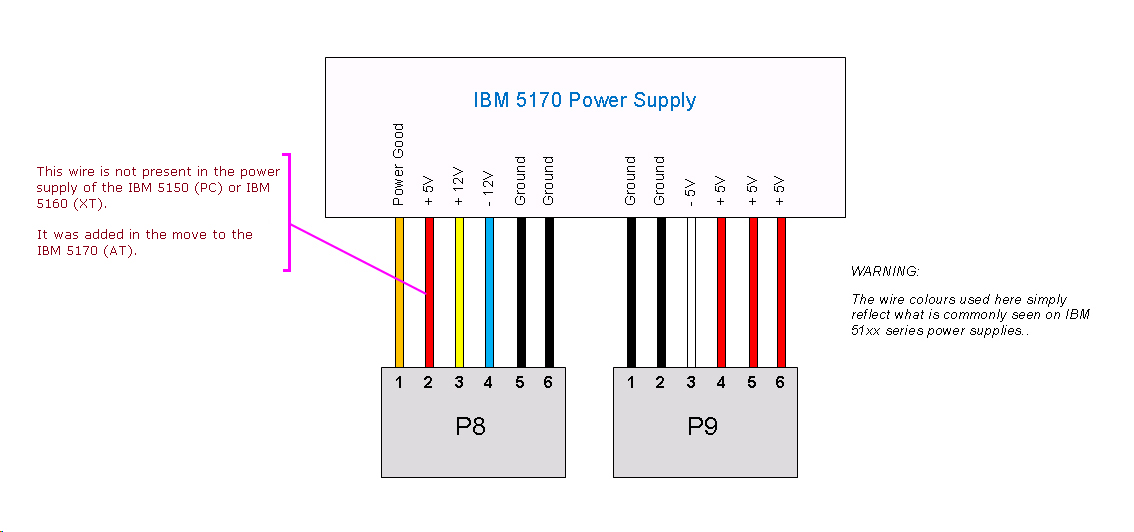
[edit | edit source]The 5170 PSU is a 192 W switcher with two motherboard connectors, P8 and P9, similar in pinout to the XT but with different rail capacities. To verify rails under load, use a digital multimeter with one probe in a chassis ground point.
| Rail | Acceptable range | Where to measure |
|---|---|---|
| +5 V | +4.75 V to +5.25 V | P8/P9 red wire, any disk drive power connector red wire |
| +12 V | +11.40 V to +12.60 V | Disk drive power connector yellow wire |
| −5 V | −4.75 V to −5.25 V | P8/P9 white wire |
| −12 V | −11.40 V to −12.60 V | P8/P9 blue wire |
The 5170 PSU requires a minimum load of approximately 7.0 A on +5 V and 2.5 A on +12 V to start. Submodels shipped without a hard drive include a 5 Ω 50 W power resistor on the +12 V hard drive power connector to satisfy the +12 V minimum. The resistor draws about 2.4 A in normal operation and is normally hot to the touch — that is by design, not a fault. If the resistor is missing, the PSU may fail to start until a hard drive (or equivalent load) is connected.
CMOS/RTC Battery
[edit | edit source]The 5170 stores its setup configuration (memory size, floppy/HDD types, date and time) in 50 bytes of CMOS RAM inside the Motorola MC146818 RTC chip on the motherboard. The CMOS is powered by an external 6 V battery pack connected via a 4-pin header (commonly J21 / "BAT" on Type 1 boards). The original IBM battery pack is a 4×1.5 V AA holder mounted to the rear of the case.
When the battery runs down, POST will report errors 161 (system options not set / battery failure) and often 163 (date and time not set). Replace the battery with a fresh 6 V pack of equivalent capacity. Many users substitute four AA-cells in a holder or a lithium-coin replacement; check polarity carefully before connecting because a reversed pack can damage the MC146818.
After replacing the battery, boot from the IBM PC AT Diagnostics diskette and run SETUP to re-enter the date, time, memory size and drive types.
Connector Care
[edit | edit source]- The AT keyboard uses a DIN-5 connector with an AT protocol that is electrically different from the XT's. Do not force an XT or PS/2 keyboard onto an AT without a protocol converter.
- The parallel and serial connectors on the IBM Serial/Parallel Adapter card are DB-25; later third-party cards may use DB-9 for the serial port.
- The IBM Fixed Disk and Diskette Drive Adapter (the "combo card") uses 34-pin (floppy) and 20-pin (hard drive data) and 34-pin (hard drive control) ribbon cables. Pin 1 is marked on each connector. Reversing a cable does not normally damage the drive but the drive will not respond.
- The +12 V load resistor (in diskette-only submodels) is a wirewound resistor in the hard drive power lead. Do not remove it unless replacing it with a real drive on that connector.
Capacitor Health
[edit | edit source]Tantalum capacitors throughout the 5170 motherboard and on most IBM AT-era ISA cards can fail short-circuit, causing the PSU to refuse to start or causing intermittent boot symptoms. The full procedure for diagnosing and replacing tantalums is in IBM PC AT Capacitor Replacement Guide.
Electrolytic capacitors in the AT switching PSU age and may need replacement after decades of storage. Symptoms include reduced or unstable output, refusal to start, audible whine or visible bulging.
Floppy Drive
[edit | edit source]- The 5170 ships with a 1.2 MB high-density 5.25" drive, half-height. Common drives include the IBM-branded Mitsubishi M4853 and Tandon TM65-2L.
- Use only high-density (HD) media in a 1.2 MB drive. Writing to a 360 KB diskette in a 1.2 MB drive may produce a diskette that cannot be reliably read in a 360 KB drive afterwards.
- Clean the heads periodically with a head-cleaning diskette or with isopropyl alcohol on a foam swab (drive off, by hand-rotating the spindle). Do not use cotton-tipped swabs.
Hard Drive
[edit | edit source]- CMI 5616 (20 MB) and CMI 6426 (30 MB) drives, shipped on early ATs, are famously unreliable. Many enthusiasts retire them in favour of more reliable replacements such as the Seagate ST-225 or ST-251 with an XT-IDE or modern SCSI/MFM adapter.
- If the hard drive is not detected, suspect: dried-out spindle bearing (drive does not spin up), head stiction, bad MFM cable, controller card seating, or PSU output sag.
- Do not attempt to low-level format an unknown drive without verifying the head/cylinder/sector geometry against the drive's label or the AT SETUP table.
ROM and CMOS Setup
[edit | edit source]SETUP is a disk-based utility on the IBM PC AT Diagnostics or Reference diskette. There is no built-in setup screen in IBM's BIOS. Many AT-class third-party motherboards have a ROM-based SETUP; the original IBM 5170 does not.
To enter SETUP:
- Boot the AT Diagnostics diskette (issued with the original system; available as an image from minuszerodegrees.net and other archives).
- Select SETUP from the menu.
- Configure memory size, installed diskette drives, fixed disk type (use the table in the diagnostics menu), and the date and time.
- Save and reboot.
Battery-Recommended Tools
[edit | edit source]- Philips #2 screwdriver and a 5/16" hex driver (case and slot brackets).
- Anti-static strap connected to chassis ground.
- Digital multimeter.
- Compressed air can or rechargeable air duster.
- Lint-free wipes and isopropyl alcohol.
- Spare 6 V battery pack for CMOS.
- Soldering iron with a fine tip, lead-free solder, and a desoldering tool or braid for capacitor work. See IBM PC AT Capacitor Replacement Guide for full requirements.
Related Pages
[edit | edit source]- IBM PC AT (5170)
- IBM PC AT Troubleshooting Guide
- IBM PC AT Capacitor Replacement Guide
- IBM PC XT Maintenance Guide — preceding model
- IBM PC (5150) Maintenance Guide — preceding model
- Recommended Tools
References
[edit | edit source]- IBM, Personal Computer AT — Technical Reference (March 1984, IBM 1502243; September 1985, IBM 6280070).
- IBM 5170 — Motherboard Versions, minuszerodegrees.net.
- IBM 5170 PSU pinout (P8/P9), minuszerodegrees.net.