

IBM PCjr Capacitor Replacement Guide: Difference between revisions
Add the PCjr internal teardown photograph alongside the power supply description |
Link the documentation page for each cited manual, keeping the File: link as the direct download |
||
| Line 8: | Line 8: | ||
== How the PCjr is powered == | == How the PCjr is powered == | ||
The PCjr uses what IBM calls a '''two-stage''' supply, and what it does is split in an unusual way:<ref name="tr">IBM, ''IBM PCjr Technical Reference'', "System Power Supply" and its Operating Characteristics, Over-Voltage/Over-Current Protection and Connector Specifications subsections. Source for the two-stage 33 W description, the transformer's short-circuit-protected extra-low ac output, the internal Power Board that converts that ac to three dc levels, the three dc rails and their regulation tolerances and load currents, the +5 V minimum load required for −6 V to be present, the input requirements, the transformer connector pinout, and the input and output protection tables. Hosted on this wiki as [[:File:IBM PCjr Technical Reference.pdf]].</ref> | The PCjr uses what IBM calls a '''two-stage''' supply, and what it does is split in an unusual way:<ref name="tr">IBM, ''IBM PCjr Technical Reference'', "System Power Supply" and its Operating Characteristics, Over-Voltage/Over-Current Protection and Connector Specifications subsections. Source for the two-stage 33 W description, the transformer's short-circuit-protected extra-low ac output, the internal Power Board that converts that ac to three dc levels, the three dc rails and their regulation tolerances and load currents, the +5 V minimum load required for −6 V to be present, the input requirements, the transformer connector pinout, and the input and output protection tables. Hosted on this wiki as [[IBM PCjr Technical Reference]] ([[:File:IBM PCjr Technical Reference.pdf|PDF]]).</ref> | ||
* '''Stage one is the external "brick" — and it is a transformer, nothing more.''' It steps mains down to a short-circuit-protected, extra-low '''ac''' voltage. IBM's connector specification for its output reads "Pin 1 – 17 Vac, Pin 2 – GND, Pin 3 – 17 Vac". There is no rectifier, no switching regulator and no high-voltage bulk capacitor inside it. Its mains cord is 3.08 m (10.16 ft) long.<ref name="tr" /> | * '''Stage one is the external "brick" — and it is a transformer, nothing more.''' It steps mains down to a short-circuit-protected, extra-low '''ac''' voltage. IBM's connector specification for its output reads "Pin 1 – 17 Vac, Pin 2 – GND, Pin 3 – 17 Vac". There is no rectifier, no switching regulator and no high-voltage bulk capacitor inside it. Its mains cord is 3.08 m (10.16 ft) long.<ref name="tr" /> | ||
Latest revision as of 08:59, 27 September 2026

This guide covers capacitor work on the IBM PCjr (model 4860) — the system board, the sidecars, and the machine's unusual two-stage power supply.
Read the power supply section before opening anything. The PCjr's power arrangement is not like the 5150's, the 5160's or any other machine in the IBM PC family, and treating it as though it were leads to both wrong diagnoses and unnecessary risk.
How the PCjr is powered
[edit | edit source]The PCjr uses what IBM calls a two-stage supply, and what it does is split in an unusual way:[1]
- Stage one is the external "brick" — and it is a transformer, nothing more. It steps mains down to a short-circuit-protected, extra-low ac voltage. IBM's connector specification for its output reads "Pin 1 – 17 Vac, Pin 2 – GND, Pin 3 – 17 Vac". There is no rectifier, no switching regulator and no high-voltage bulk capacitor inside it. Its mains cord is 3.08 m (10.16 ft) long.[1]
- Stage two is the Power Board inside the system unit. This is the printed-circuit board that rectifies and regulates the transformer's ac output into the machine's three dc rails. It connects directly to the system board, and carries the diskette drive power connector and the drive fan connector on its front edge, plus the machine's power switch on its rear.[1]
Two consequences follow immediately:
- The electrolytic capacitors that age in a PCjr are on the Power Board inside the system unit, not in the brick.
- The over-current protection that trips when a capacitor shorts is on the Power Board, not in the brick. It is not a "fold-back" that makes the brick click on and off.
The rails are +5 V, +12 V and −6 V — not the −5 V and −12 V of the 51xx family.[1] The whole supply is rated at 33 W. The Power Board itself came in two lengths over the machine's production life, the short one rated at 33 W and the long one at 45 W.[2]
| Rail | Load current, min | Load current, max | Regulation tolerance | Acceptable range |
|---|---|---|---|---|
| +5 V | 1.5 A | 3.6 A | ±5 % | +4.75 to +5.25 V |
| +12 V | 0.04 A | 1.2 A | ±5 % | +11.40 to +12.60 V |
| −6 V | 0.0 A | 0.025 A | ±16 % | −5.04 to −6.96 V |
There must be a minimum load of 1.5 A on +5 V for the −6 V rail to be present at all.[1] A missing −6 V on a lightly loaded bench setup is therefore not necessarily a fault.
A fully configured machine — internal modem, 64 KB memory expansion and diskette drive, but no sidecars — leaves roughly 400 mA of +5 V for sidecars. That is not much, and a heavy or numerous sidecar load produces flaky operation rather than a clean failure. A "power" sidecar was sold to add capacity, and it uses the same external transformer.[2]

Protection behaviour
[edit | edit source]Knowing what the protection actually does is what turns a symptom into a diagnosis.[1]
| Where | Type | Threshold / behaviour |
|---|---|---|
| Transformer input | Non-resettable fuse, plus thermal/over-current | A blown transformer fuse is not user-resettable. |
| Power Board, +5 V over-voltage | Fuse | Trips at 6.3 ± 0.7 Vdc |
| Power Board, +12 V over-voltage | Fuse | Trips at 14.4 ± 1.4 Vdc |
| Power Board, +5 V over-current | Resettable | Trips at about 3.9 A |
| Power Board, +12 V over-current | Resettable | Trips at 2.2 ± 0.9 A |
The over-current protection is resettable by removing the fault condition for at least five seconds and then re-applying power.[1] That is the behaviour to expect from a shorted capacitor: the machine will not run, and it will keep not running until the short is removed. Over-voltage protection, by contrast, is by fuse — a Power Board that has been through an over-voltage event may need more than the fault cleared.
Motherboard capacitor list
[edit | edit source]IBM published no component-level capacitor list for the PCjr: the only capacitor entries in the text of the PCjr Technical Reference are glossary definitions.
The Console5 Tech Wiki publishes a designator-level list, derived from working on the boards rather than from an IBM document. It is a secondary source and is given here as such — check the markings on the parts in your own machine before ordering.[3]
| Board | Designators and values |
|---|---|
| Main board | C2, C4, C8, C12, C13, C22, C35, C38, C39, C45, C59 — all 10 µF / 16 V |
| Power Board (33 W) | C1 1000 µF / 16 V; C2 100 µF / 16 V; C3 22 µF / 25 V; C4 1000 µF, low ESR; C13 15000 µF / 25 V |
| IR receiver board | C1, C4, C6 — 10 µF / 50 V |
| 64 KB memory card | C1 — 10 µF / 16 V |
| Diskette controller | C1 1 µF / 50 V; C5 10 µF / 16 V |
Two observations about that list are worth drawing out.
The main board positions are not a tidy consecutive run, which is what real board numbering looks like. All eleven are the same 10 µF / 16 V value, consistent with the tantalum filter capacitors used across the IBM 51xx boards of the period.[4] Note that minuszerodegrees.net's tantalum documentation names the 5150, 5155 and 5160; it does not cover the 4860, so the family resemblance here rests on the Console5 list and on the parts themselves, not on a source that names the PCjr.
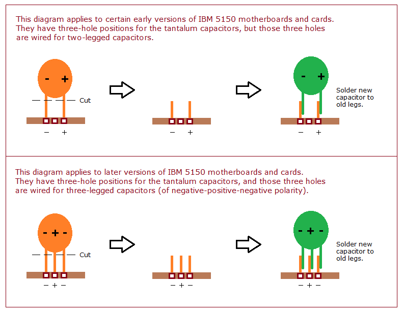
The Power Board list contains nothing high-voltage. C13 at 15000 µF / 25 V is the large smoothing capacitor that follows the rectifier fed by the 17 Vac transformer, and it is the biggest thing on the board. Console5 notes that the original is a three-legged part with very wide lead spacing, that modern replacements are smaller two-legged parts, and that the board already carries solder points supporting the newer spacing — a slight change of orientation is all that is required.[3] The "1000 µF / 12 V" rating listed for C4 is not a standard capacitor voltage; read the marking on your own part rather than ordering to that figure.
Failure Modes
[edit | edit source]The tantalum filter capacitors fail in two ways:[5]
- Open circuit — filtering is lost but the rail still rises. The machine may still run and simply be more sensitive to noise. Capacitors serving dynamic RAM are the ones where this matters most.[6]
- Short circuit — the capacitor pulls its rail down and overloads the supply, which will not then run.[5] On a PCjr that means the Power Board's over-current protection holding the machine off until the fault is removed.[1]
Failures happen overwhelmingly on application of power, or within about thirty seconds of it, and the rate is high for a machine left unpowered for years and low for one used every few months.[5] They are sometimes dramatic, so eye protection on first power-up of an unknown board is sensible.
Many failed tantalums show no visible damage at all.[5]

The aluminium electrolytics on the Power Board age differently: they dry out over decades, producing sagging or unstable rails, ripple, and a supply that works cold and misbehaves warm.
Diagnostic Procedure
[edit | edit source]The PCjr gives you less to go on than a 5150 or 5160 does. It has no fan of its own — a machine with a diskette drive has a fan on the drive, fitted to stop the diskette cooking rather than to cool the system — so "the fan spins but nothing happens" is not a symptom available here.[2]
- Disconnect the external transformer at the wall and at the system unit.
- Open the system unit and remove all sidecars and both cartridges. A shorted capacitor on a sidecar produces exactly the same symptom as one on the system board.
- Inspect the system board tantalums. Most failures leave no mark, so a clean inspection proves nothing.
- With a multimeter on a low resistance or diode range, probe across each tantalum in circuit — negative probe to ground, positive probe to the rail side. Remember the rails here are +5 V, +12 V and −6 V. A good tantalum reads high after a brief charging pulse; a shorted one reads close to zero.
- Where a short is found, remove the capacitor to confirm. Other components on the same rail can produce a false short.
- After clearing a fault, leave the machine off for at least five seconds before re-applying power — that is what resets the Power Board's over-current protection.[1]
- If nothing on the system board is shorted, refit the sidecars one at a time. The one that reintroduces the failure has the fault.
Bear in mind that a machine which will not start with several sidecars fitted but is fine with fewer may not have a fault at all — it may simply be past the roughly 400 mA of spare +5 V the supply has to give.[2]
Removal and Replacement
[edit | edit source]- Photograph or mark the polarity of the original before removing it.
- Add fresh solder and flux to both pads to wet the old joint.
- Heat one pad, lever that side of the capacitor up, then heat the other and lift the part clear.
- Clear the holes with wick.
- Fit the replacement with the + on the capacitor matching the + on the silkscreen.
- Solder from the underside, inspect for a clean fillet, and trim the legs.
The like-for-like replacement for the motherboard positions is a 10 µF / 16 V tantalum, or a part of higher voltage rating; nothing below 16 V.[4] Solid polymer tantalums of the same value are a reasonable substitute because they do not have the short-circuit failure mechanism — a choice about failure mode, not a claim about what IBM fitted.
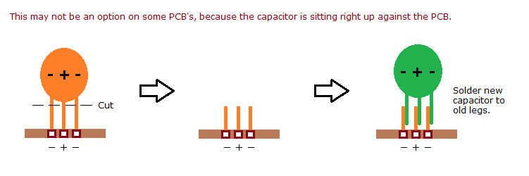
Where a capacitor's legs allow it, the cut-and-graft technique minuszerodegrees.net names SNCTOL — "solder new capacitor to old legs" — avoids reheating the pads entirely: cut the old capacitor's legs a few millimetres above the board, lift the body away, and solder the new part to the stubs left in the holes.[7]

Power Board Recap
[edit | edit source]The board to recap is the one inside the system unit, and the capacitor list above is the starting point for it.
This board is fed with low-voltage ac from the transformer, so its capacitors are low-voltage parts and there is no mains-derived high-voltage bulk capacitor on it. That materially changes the risk compared with recapping a 5150, 5160 or 5170 supply. It does not remove the need to unplug the machine at the wall first, and the transformer itself is a mains-connected assembly that should be left closed and unplugged while you work.
Procedure:
- Unplug the transformer from the wall and from the system unit.
- Open the system unit and remove the Power Board.
- Discharge C13 — the large smoothing capacitor — through a resistor and confirm with a meter before handling the board. It is a low-voltage part, but 15000 µF holds a meaningful amount of charge.
- Replace each electrolytic with a new low-ESR part of equal capacitance, equal or higher voltage rating, and equal or higher temperature rating. 105 °C in place of 85 °C is a reasonable upgrade.
- For C13, note that the original is a wide-spaced three-legged part and a modern two-legged replacement fits the solder points already on the board with a slight change of orientation.[3]
- Refit and verify the three rails against the table above, remembering that −6 V will not appear without at least 1.5 A on +5 V.[1]
Sidecar Capacitors
[edit | edit source]Each sidecar draws its power from the system unit's sidecar bus and carries its own filter capacitors. A shorted capacitor on a sidecar produces the same symptom as one on the system board.
Console5's list covers a few of the PCjr's attachments — the 64 KB memory card (C1, 10 µF / 16 V) and the diskette controller (C1 1 µF / 50 V, C5 10 µF / 16 V) among them.[3] No comprehensive per-sidecar map is published, and this wiki has not measured one. Diagnose behaviourally: remove all sidecars and re-add them one at a time.
Post-Recap Verification
[edit | edit source]- The PCjr's POST ends with one short beep when it completes without error — the BIOS listing in IBM's Technical Reference labels that case "1 SHORT BEEP (NO ERROR)".[1]
- Verify each rail against the table above, under load rather than open-circuit.
- If the machine starts but a particular sidecar still drops it, re-inspect that sidecar — and check the power budget before assuming a fault.[2]
- Ripple on the rails showing up as noise on the display points back at the Power Board electrolytics.
References
[edit | edit source]- ↑ 1.00 1.01 1.02 1.03 1.04 1.05 1.06 1.07 1.08 1.09 1.10 IBM, IBM PCjr Technical Reference, "System Power Supply" and its Operating Characteristics, Over-Voltage/Over-Current Protection and Connector Specifications subsections. Source for the two-stage 33 W description, the transformer's short-circuit-protected extra-low ac output, the internal Power Board that converts that ac to three dc levels, the three dc rails and their regulation tolerances and load currents, the +5 V minimum load required for −6 V to be present, the input requirements, the transformer connector pinout, and the input and output protection tables. Hosted on this wiki as IBM PCjr Technical Reference (PDF).
- ↑ 2.0 2.1 2.2 2.3 2.4 Mike Brutman, IBM PCjr Hardware, "The Power Supply" section. Source for the split supply description, the short and long Power Board variants rated at 33 W and 45 W, the roughly 400 mA of +5 V left for sidecars on an internally fully configured machine, the behaviour of overloaded sidecar configurations, the existence of power sidecars using the same external transformer, and the point that the system has no fan of its own while a diskette-equipped machine has a fan on the drive.
- ↑ 3.0 3.1 3.2 3.3 IBM PCjr, Console5 Tech Wiki. Secondary source. A community-maintained capacitor list with per-designator values for the PCjr main board, the 33 W Power Board, the IR receiver board, the 64 KB memory card and the diskette controller, together with annotated cap-map images and system board schematics. The list is compiled from the boards themselves rather than from IBM documentation.
- ↑ 4.0 4.1 Tantalum capacitors on IBM 51xx motherboards/cards, minuszerodegrees.net, together with its 2-legged and 3-legged pages. Source for the 10 µF/16 V value and its "106 16V" markings, the three-hole footprint and its two wiring variants, the negative-positive-negative polarity of the 3-legged variant, and the Kemet/Mouser replacement part numbers. These pages state their scope as the IBM 5150, 5155 and 5160 — not the PCjr.
- ↑ 5.0 5.1 5.2 5.3 Commonly Failing Electronic Components (in vintage computers), minuszerodegrees.net. Source for the open-circuit and short-circuit failure modes of tantalum capacitors, the overloading of the supply by a short, the observation that a failure usually occurs on application of power or within about thirty seconds, the difference in failure rate between machines left unpowered for years and machines used regularly, and the fact that failures are sometimes dramatic.
- ↑ Vintage Computers — Filter Capacitors, minuszerodegrees.net. Explains the filtering role, notes that capacitors serving dynamic RAM are crucial while others may not be, and advises fitting a new capacitor whenever you cannot judge which case applies.
- ↑ SNCTOL diagram and its 5150 variant, minuszerodegrees.net. Both carry the instruction "Solder new capacitor to old legs" and show the cut-and-graft sequence; both note the method is unavailable where the capacitor sits hard against the PCB. The diagrams are drawn for IBM 51xx boards.
Related Pages
[edit | edit source]- IBM PCjr
- IBM PCjr Maintenance Guide
- IBM PCjr Troubleshooting Guide
- IBM PC (5150) Capacitor Replacement Guide
- IBM PC XT Capacitor Replacement Guide
- Capacitor Failure Symptoms