Grandstand The Big Game Soccer Capacitor Replacement Guide

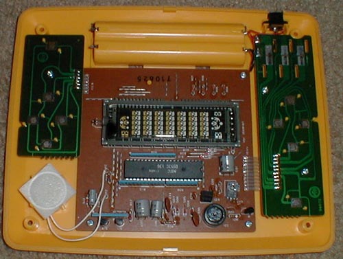
The Grandstand The Big Game Soccer has four electrolytic capacitors on its main board. Their values and positions are known from a 2026 repair of Epoch's Exciting Soccer Game, the same game, in which all four were replaced; the photographs show the old parts before and after removal.[1] The Handheld Museum's photograph of an opened Grandstand unit shows the same board layout and the same microcontroller,[2] but its 500-pixel resolution is too low to read capacitor values, so check your own board against the table before ordering.
Signs that the capacitors need attention
[edit | edit source]- The game will not power up, or the display is dim on fresh cells.[1]
- Brown residue or corrosion on the board round a capacitor, or a domed top.
- See Capacitor Failure Symptoms.
Big Game Soccer capacitor list
[edit | edit source]| Position | Original part | Fitted by the repairer | Where |
|---|---|---|---|
| C01 | 330 µF 16 V (blue, 85 °C) | 330 µF 16 V, Nippon Chemi-Con KMG | Beside the D882 power transistor at S03, near the flat cable to one control board |
| C06 | 47 µF 50 V (light blue) | New part, value not legible in the photographs | Right of C07, between the microcontroller and the transformer |
| C07 | 220 µF 16 V (grey) | New part, value not legible in the photographs | Left of C06 |
| C10 | 10 µF 16 V (small, blue) | 10 µF 50 V, Nippon Chemi-Con KMG | Beside the speaker leads, at the opposite end of the board from C01 |
Each value was read from the removed parts photographed in front of the board, and matched to its position by comparing the board before and after the work: the grey part at C07, the light-blue part at C06, the blue part at C01 and the small blue part at C10.[1]
Replacement procedure
[edit | edit source]- Remove the battery door and cells, the four corner screws and the top shell, then lift the white stadium moulding off; see Grandstand The Big Game Soccer General Maintenance.
- Photograph the flat cables to the two control boards and the red and black leads to the battery holder and DC socket.
- Free the main board. Lay it on a soft cloth with the display tube uppermost and keep the iron away from the tube's glass and its sealed tip.
- Note the polarity of each capacitor before removing it, and replace one at a time.
- C06 and C07 sit side by side; change them one after the other, not together, so their values cannot be swapped.
- Clean off flux with isopropyl alcohol and reassemble.
Recommended parts
[edit | edit source]- 330 µF 16 V (C01), 47 µF 50 V (C06), 220 µF 16 V (C07) and 10 µF 16 V or higher (C10), radial, 105 °C, of a height that clears the stadium moulding.
- A temperature-controlled soldering iron, desoldering braid or pump, flux and isopropyl alcohol.
After the recap
[edit | edit source]Power the board from a 6 V bench supply or fresh cells before closing the case, as the repairer did with clip leads.[1] The display should light with both teams and the score, and the keys at both ends should move their players.[3] If the game still will not power up, test the D882 at S03 and the small C945 transistors at S11 and S12; one of these is shown removed in the repair's photographs.[1]
Warning: keep fingers off the transformer while the board is powered. On Astro Wars, built round the same kind of converter, the winding was measured at about 200 V peak to peak.[4]
Related pages
[edit | edit source]- Grandstand The Big Game Soccer
- Grandstand The Big Game Soccer General Maintenance
- Grandstand The Big Game Soccer Troubleshooting Guide
- Capacitor Failure Symptoms
References
[edit | edit source]- ↑ 1.0 1.1 1.2 1.3 1.4 1.5 analo9, "1981 에포크 VFD 휴대용 축구 게임기 (EPOCH Exciting Soccer)", 아날로그 탐구생활 (Naver blog, in Korean), 28 April 2026 (retrieved 2026-10-18); the same repair on YouTube as "1981 에포크 VFD 휴대용 축구 게임기 (EPOCH Exciting Soccer LSI Game repair)". An Epoch Exciting Soccer Game that would not power up, "disassembled and repaired" (the post's only text). Its 38 photographs, examined at full size (1,280 × 717 pixels), show: the Japanese box (デジコムサッカー, code no. 36070, "four AA (単III) batteries or AC adapter (sold separately)"); the base, with a screw hole at each corner and a separate battery door; the case opened, with the white stadium moulding and its green pitch print over the main board, the speaker in a white foam pad at one corner, a control board at each side with rubber keys, and the DC socket on red and black leads at one corner beside the battery holder; inside the top shell, a violet filter sheet over the display window; the main board, with an NEC microcontroller marked "D553C 136" and "E13326", the display tube at position V01 beside the silkscreen "10AM18T", with its sealed glass tip at one end, an NEC D882 power transistor at S03, a round TDK transformer marked TY-33 at I01, diodes S04 to S10 and S13, transistors marked C945 at S11 and S12, and four electrolytic capacitors: C01 (beside S03), C06 and C07 (side by side near the transformer) and C10 (beside the speaker leads); the four old electrolytics after removal, marked 330 µF 16 V, 47 µF 50 V, 220 µF 16 V and 10 µF 16 V, and the board before and after, showing that the grey part at C07 was the 220 µF, the light-blue part at C06 the 47 µF, the blue part at C01 the 330 µF and the small blue part at C10 the 10 µF; new Nippon Chemi-Con KMG parts in place, legible as 330 µF 16 V at C01 and 10 µF 50 V at C10; a removed C945 transistor and a resistor beside the board; clear flat cables joining the control boards to the main board; the game running on the bench from clip leads and then reassembled.
- ↑ Handheld Museum, "Game Guts", photograph Grandstand-BigGameSoccerGuts.jpg (500 × 377 pixels, retrieved 2026-10-18), examined at full size: a Grandstand unit opened, with the main board in the centre carrying the display tube and an NEC microcontroller whose label, upside down, reads "D553C 13" and a last digit not clear at this size; a holder for four cells along the top; the DC socket at the top right; a control board at each side; the speaker at the lower left; the round transformer at the lower right.
- ↑ Handheld Museum, "Grandstand The Big Game Soccer" and "Epoch Exciting Soccer Game" (retrieved 2026-10-18). The Grandstand game: 1981, VFD, four AA batteries, "Licensed from Epoch (Exciting Soccer Game)"; Epoch's: 1981, VFD, four AA batteries, "Sold in the U.K. by Grandstand as Kevin Keegan's The Big Game Soccer and in Germany by GAMAtronic as Fussball-Spiel". The photographs, examined: the Grandstand game, yellow, with "THE BIG GAME SOCCER" and "GRANDSTAND" on the green pitch printing, four direction keys and a SHOOT button at each end, POWER OFF/ON, LEVEL AMA/PRO and PLAYER 1/2 switches at the left, and a speaker grille at the right; the lit display, with red players for one side and blue for the other; the box ("THE BIG GAME ELECTRONIC SOCCER", Kevin Keegan roundel, "EXCITING ELECTRONIC SOUND EFFECTS", "2-COLOR FLUORESCENT DISPLAY WITH SHAPED PLAYERS").
- ↑ Handheld Museum forum, "Astro wars / galaxy ii repair", pages 1 and 2, December 2018 to January 2019 (retrieved 2026-10-18): on Grandstand Astro Wars (Epoch Galaxy II), whose display supply is a D882 switching 6 V into a TDK transformer, the dead game's D882 ran hot and the supply fell to about 1.5 V; diode S06 read about 20 Ω both ways, and the game worked once S06 was replaced; with S06 removed, the full −10 V reached the μPD553 microcontroller. On a working game the owner measured about 200 V peak to peak on the transformer winding with a basic oscilloscope he said was probably not accurate at that level.