

Apple IIe
 | |
| Apple IIe | |
| Specifications | |
|---|---|
| Manufacturer | Apple Computer, Inc. |
| Type | Home computer |
| Released | January 1983 |
| Discontinued | February 1985 (replaced by the Enhanced IIe); the IIe line ran to November 1993 |
| Intro price | US$1,295, 64K system (A2S2064), February 1984 |
| CPU | 6502B at 1 MHz |
| Memory | 64 KB RAM, 16 KB ROM; 128 KB with an extended 80-column card |
| Storage | Cassette interface; Disk II 5.25-inch floppy and other drives through slot cards |
| Display | 40×24 text; 80×24 with an 80-column card; 40×48 low-resolution 16 colours; 280×192 high-resolution; 560×192 double high-resolution on Rev. B and later boards |
| Sound | Speaker toggled at $C030 |
| OS / Firmware | Apple DOS 3.3, ProDOS, CP/M with a Z-80 card |
| Predecessor | Apple II Plus |
| Successor | Apple IIe Enhanced |
| Codename | Diana, later LCA ("Low Cost Apple"), finally Super II |
| Model no. | A2S2064 (64K system) |
The Apple IIe (styled "Apple //e") is the third model in the Apple II series, introduced in January 1983. The original version was replaced by the Enhanced IIe in March 1985 and the Platinum IIe in January 1987, and the IIe was removed from Apple's price lists in November 1993.[1] Apple's February 1984 dealer price list gives $1,295 for the Apple //e 64K System, A2S2064.[2]
Architecture and processor
The IIe uses a 6502B, a high-speed version of the 6502, running at 1 MHz.[3]
Walt Broedner's design gets 80-column text by mirroring the 40-column text screen into a parallel 1 KB space, even columns in one bank and odd columns in the other. Extending the same idea to the whole 64 KB address space gives 128 KB of bank-switched memory. The extra memory goes on a card in the auxiliary slot, which takes the place of slot 0: either a 1 KB 80-column card or a 64 KB extended 80-column card. The 80-column firmware is mapped to slot 3.[1] Broedner, Peter Quinn and their team cut the main board from over a hundred components to thirty-one.[1]
The open-apple and solid-apple keys either side of the space bar are wired to push-buttons 0 and 1 of the game port.[1]
Memory and storage
The IIe has 64 KB of RAM on the main board, and 128 KB with an extended 80-column card in the auxiliary slot.[4][1] The firmware is in two ROMs, named CD and EF after the address ranges they occupy; they hold Applesoft, the Monitor, the 80-column firmware and the self-test.[4] Cassette input and output are on the back panel.[3] Disk drives connect through controller cards in the slots.
Board revisions
Apple's service notes identify three versions of the IIe logic board:[5]
| Rev. A | Rev. B | Enhanced | |
|---|---|---|---|
| Manufacturing number (last two digits and revision letter) | 64-A | 64-B | 87-A |
| Microprocessor at B4 | 6502 | 6502 | 65C02 |
| Date on the board | 1982 | 1982 | 1984 |
| Heading on the monitor at power-up | Apple ][ | Apple ][ | Apple //e |
Revision B added the hardware for double high-resolution graphics and a soft switch to turn it on.[1] Apple's instruction is that a Rev. A unenhanced board must be upgraded to a Rev. B unenhanced board before the Apple IIe Enhancement Kit is fitted, because the kit changes only four chips.[5][1] Apple sold its remaining Rev. A boards in bulk to value-added resellers; those boards are stamped "VAR" on both sides and were not eligible for Apple's exchange programme.[5]
Early boards whose part number ends in -A also lack the composite sync and 3.58 MHz colour reference signals on slot 7.[3]
Display and graphics
| Mode | Resolution and colour |
|---|---|
| Text | 40×24; 80×24 with an 80-column card in the auxiliary slot |
| Low-resolution graphics | 40×48, 16 colours |
| High-resolution graphics | 280×192, 6 colours |
| Double high-resolution graphics | 560×192 monochrome or 140×192 in 16 colours, on Rev. B and later boards with 128 KB |
Video output is NTSC composite. The auxiliary slot carries all the video signals, which is why RGB and 80-column cards go there.[3][4]
Input/output and expansion
- Seven peripheral slots numbered 1 to 7, and the 60-pin auxiliary slot[3]
- Game I/O on a 16-pin internal socket and a 9-pin D-type connector on the back panel. Each of the four hand-control inputs takes a variable resistance of up to 150K ohms to +5 V.[3]
- Composite video output; cassette input and output
- Built-in keyboard
The shift-key modification
The single-wire shift-key modification lets software read the SHIFT key through game button 2. The 1982 Reference Manual tells owners to make it by soldering across the broken circle marked X6 on the main board, and says early boards whose part number ends in A already have it.[3] Apple's later Technical Procedures say the modification was not present on Rev. A and Rev. B boards and is hard-wired on later ones; X6 is to the left of the keyboard connector.[6]
On a board with X6 joined, pressing SHIFT while a hand-control switch on button 2 is closed shorts +5 V to ground and the power supply shuts down, losing anything in memory.[3][6] Apple's fix is to cut between the two X6 pads with a craft knife and check with an ohmmeter that they no longer connect.[6]
Power supply
Apple published a full specification for the IIe supply, with per-rail tolerances.[3]
| Parameter | Value |
|---|---|
| Line voltage | 107 V to 132 V AC |
| Maximum power consumption | 60 W continuous; 80 W intermittent |
| Supply voltages | +5 V ±3% (4.85-5.15 V); +11.8 V ±6% (11.09-12.51 V); −5.2 V ±10%; −12 V ±10% |
| Maximum supply currents | +5 V 2.5 A; +12 V 1.5 A continuous, 2.5 A intermittent; −5 V 250 mA; −12 V 250 mA |
| Maximum case temperature | 55 °C (130 °F) |
Apple defines intermittent operation as up to twenty minutes at the higher load followed by at least ten minutes at normal load. The nominal "+12 V" rail is specified as +11.8 V and the "−5 V" rail as −5.2 V. Running the IIe from a source above 140 V damages the supply.[3]
The supply turns off all four outputs when it detects a supply voltage shorted to ground, a disconnected power-supply cable, or any supply voltage out of range. It then restarts about every half second until the fault clears or the power is switched off.[3]
Apple's service replacement is 661-0455, listed as the Apple II and IIe power supply; its fuse is 740-0001, 1 A 250 V.[7] A later replacement supply is 1.5 inches longer than the original and fits any IIe; it looks like the Apple IIGS supply but the two are not interchangeable.[5]
Mains potential is present on the primary side, and Apple's 1982 manual describes the supply as sealed because some of its circuits connect directly to the power line. See Apple II General Maintenance for the hazards and the procedure.[3]
Chip locations
Apple's layout drawing of the U.S. logic board uses a grid of columns A to F and rows 1 to 14.[6] The positions below are those given by the community Apple IIe Repair Guide; its rows agree with Apple's drawing except for the two firmware ROMs.
| Position | Device | Apple part number | |||
|---|---|---|---|---|---|
| B4 | 6502 CPU (65C02 on enhanced boards) | - | D1 | PAL 16R8 | 342-0170 |
| D4 | MMU | 344-0010 | |||
| D6 | IOU | 344-0020 | |||
| Row 8 | CD ROM | 342-0135 (enhanced 342-0304) | |||
| Row 10 | EF ROM | 342-0134 (enhanced 342-0303) | |||
| D12 | Keyboard ROM | 342-0132 | |||
| D14 | Keyboard encoder | 332-9600 | |||
| F4 | Character generator ROM | 342-0133 (enhanced 342-0265) | |||
| F6-F13 | 64K RAM (eight chips) | 334-0003 |
Apple's drawing places the CD ROM at row 8 and the EF ROM at row 10, and the photograph in Apple's Enhancement Kit sheet shows the same order, CD to the left of EF seen from the front.[9] The community guide lists them the other way round (EF ROM at D8, CD ROM at D10). Apple's symptom chart also refers to a character generator ROM "at location E-12", a position that holds the keyboard ROM on Apple's drawing. Check the part number on the chip before replacing it.[6][8]
Diagnostics
To run the built-in diagnostics, hold Open-Apple and Closed-Apple while switching on, or hold Control, Open-Apple and Closed-Apple and press Reset, releasing Reset first. The screen shows patterns for about a minute while the RAM, ROM and other logic board parts are tested. The result appears at the lower left: "System Good" with a high beep, or "System Bad" with a low beep. For "System Bad", or if the diagnostics cannot be reached, Apple's instruction is to exchange the keyboard or logic board.[10]
| Symptom | Apple's steps |
|---|---|
| No video | Video cable; RAM; ROMs CD and EF; logic board |
| Fuzzy display on a known-good monitor | Video cable; RAM; ROMs CD and EF; logic board |
| Garbage on a known-good monitor | RAM; ROMs CD and EF; logic board |
| Cassette saving or loading problem | Logic board |
| Keys fail the diagnostic keyboard test | Keyboard cable; keyboard; keyboard ROM; logic board |
| Intermittent lock-ups with an Extended 80-Column Card | MMU; the card; logic board |
| Display problem with an Extended 80-Column Card | 74LS245 on the card; the card; logic board |
| Numeric keypad special keys do not work | If there is a "revision C" character generator ROM at location E-12, exchange it for any other version; do not replace the logic board |
| Does not auto-boot from a UniDisk 3.5 or ProFile | Only the enhanced IIe auto-boots from these; type PR#n for the slot |
| Programs run erratically or crash | RAM; ROMs CD and EF; logic board; disk drive |
| No beep, no message, random characters, drive does not come on | ROM EF; RAM; power supply; logic board |
| Applesoft or Integer BASIC errors | ROM CD; RAM; logic board |
| No power light, no video | AC power cord; power supply; logic board |
| No audio | Speaker; logic board |
| Self-test runs at power-on | Keyboard cable; keyboard; logic board |
| Lock-up or hiss after a logic board exchange | Check the speaker wire, which may be pierced |
Things that are not faults
- A machine that powers down when SHIFT and a joystick button are pressed together has the shift-key modification made at X6.[3][6]
- A "+12 V" rail reading 11.8 V is Apple's nominal.[3]
- An unenhanced IIe does not auto-boot from a UniDisk 3.5 or ProFile.[4]
- Some parts inside the case normally get "rather warm to the touch". The first symptom of real overheating, for example from blocked ventilation slots, is erratic operation, because the memory devices are sensitive to heat.[3]
Documentation
- Apple IIe Reference Manual: specifications, power supply, I/O, firmware
- Apple IIe Technical Procedures: Apple's service manual (board identification, take-apart, diagnostics, symptom chart, enhancement kit, parts list)
Gallery
-
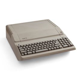
 Apple IIe
 -
 Apple IIe with a Monitor III and two Disk II drives
 -
 Apple IIe with the lid off
 -
 Apple IIe Platinum (1987)


Related pages
References
- ↑ 1.0 1.1 1.2 1.3 1.4 1.5 1.6 1.7 Steven Weyhrich, Apple II History, Chapter 7, "The Apple IIe", apple2history.org: project names Diana, LCA and Super II; Walt Broedner's 80-column and auxiliary slot design; the reduction from over a hundred components to thirty-one; the open-apple and solid-apple keys wired to game buttons 0 and 1; the Revision A and Revision B boards and double high-resolution; the model timeline (IIe January 1983 to February 1985, Enhanced March 1985 to December 1986, Platinum January 1987 to November 1993); the November 1993 removal from Apple's price lists.
- ↑ Apple Dealer Price Lists for Apple III, Apple II, Macintosh and Lisa, Apple Computer, Inc., 15 February 1984, hosted as Apple Dealer Price Lists February 1984 (PDF). Apple II section: A2S2064 Apple //e 64K System, $1,295.00.
- ↑ 3.00 3.01 3.02 3.03 3.04 3.05 3.06 3.07 3.08 3.09 3.10 3.11 3.12 3.13 3.14 3.15 Apple IIe Reference Manual (Apple II Reference Manual, For //e Only), Allen Watson, Apple Computer, Inc., 1982, product A2L2005, hosted as File:Apple IIe Reference Manual 1982.pdf. Chapter 1: the 6502B, the power supply and its sealed enclosure; Chapter 2: the single-wire shift-key modification at X6 and the hand-control warning; Chapter 7: Table 7-2 power supply specifications (p. 136), the supply's protection circuit, the 140-volt warning, environmental notes (p. 137), game I/O (150K ohm inputs, 16-pin connector), video signals on slot 7 and the auxiliary slot.
- ↑ 4.0 4.1 4.2 4.3 4.4 Apple IIe Technical Procedures, Apple Computer, Inc., in Apple Service Technical Procedures: Apple II Family, Volume One, part number 072-0229, hosted as File:Apple IIe Technical Procedures.pdf. Section 3, Troubleshooting, "Modules and Functions", pp. 3.4-3.5, and "Apple IIe Symptom Chart", pp. 3.6-3.8 (rev. Oct 88, p. 3.7 rev. Mar 92).
- ↑ 5.0 5.1 5.2 5.3 5.4 Apple IIe Technical Procedures (see above), Section 0, Service Notes, "Identification - Rev. A, Rev. B, and Enhanced", p. 0.6, and "Case and Keyboard Changes" and "Power Supply Change", p. 0.7 (rev. Aug 87).
- ↑ 6.0 6.1 6.2 6.3 6.4 6.5 6.6 Apple IIe Technical Procedures (see above), Section 4, Additional Procedures, "Single-Wire Shift-Key Modification", p. 4.4, and "Apple IIe Enhancement Kit Upgrade", pp. 4.2-4.4 (rev. Jul 87).
- ↑ 7.0 7.1 Apple IIe Technical Procedures (see above), Illustrated Parts List, "Finished Goods Assembly", p. IPL.3, "Logic Board", p. IPL.7, and "Power Supply", p. IPL.9 (rev. May 89).
- ↑ 8.0 8.1 Apple IIe Repair Guide, "Double Density", distributed by Apple2Online, mirrors.apple2.org.za. Community document, not an Apple publication: chip location table (6502B B4, HAL D1, MMU D4, IOU D6, keyboard ROM D12, AY3600 D14, video ROM F4, RAM F6-F13).
- ↑ Apple IIe Enhancement Kit: Dealer's Installation Instructions, Apple Computer, Inc., part number 030-1142-B, hosted as File:Apple IIe Enhancement Kit Dealer Installation Instructions.pdf. Figure 1, chips on the U.S. (NTSC) main logic board, p. 2.
- ↑ Apple IIe Technical Procedures (see above), Section 2, Diagnostics, "Built-In Diagnostics", p. 2.2 (rev. Oct 88).